FMB140 First Start: Difference between revisions
m Text replacement - "Bluetooth®" to "Bluetooth" |
No edit summary |
||
| (3 intermediate revisions by 2 users not shown) | |||
| Line 1: | Line 1: | ||
{{Template:FMB1_First_start_card_withoutSD|model=FMB140|description=GNSS/GSM/ | {{Template:FMB1_First_start_card_withoutSD|model=FMB140|description=GNSS/GSM/Bluetooth® tracker with integrated CAN chip, internal GNSS/GSM antennas and internal battery||pic=[[Image:FMB140_600X600_01.png|400px|right]]|dual_sim=|sim_pin=[[FMB140 Security info|'''Security info''']]}} | ||
== '''Battery placement after complete device disassembling''' == | == '''Battery placement after complete device disassembling''' == | ||
[[File:Battery placement case.png|left|313x313px]] | [[File:Battery placement case.png|left|313x313px]] | ||
| Line 57: | Line 57: | ||
| style="border: 1px solid white; border-bottom: 2px solid #E8E8E8; text-align: left; vertical-align: center; background: white;" |8 | | style="border: 1px solid white; border-bottom: 2px solid #E8E8E8; text-align: left; vertical-align: center; background: white;" |8 | ||
| style="border: 1px solid white; border-bottom: 2px solid #E8E8E8; text-align: left; vertical-align: center; background: white;" |DOUT 1 | | style="border: 1px solid white; border-bottom: 2px solid #E8E8E8; text-align: left; vertical-align: center; background: white;" |DOUT 1 | ||
| style="border: 1px solid white; border-bottom: 2px solid #E8E8E8; text-align: left; vertical-align: center; background: white;" |Digital output, channel 1. Open collector output. Max. | | style="border: 1px solid white; border-bottom: 2px solid #E8E8E8; text-align: left; vertical-align: center; background: white;" |Digital output, channel 1. Open collector output. Max. 0,5 A DC. | ||
|- FFA500 | |- FFA500 | ||
| style="border: 1px solid white; border-bottom: 2px solid #E8E8E8; text-align: left; vertical-align: center; background: white;" |9 | | style="border: 1px solid white; border-bottom: 2px solid #E8E8E8; text-align: left; vertical-align: center; background: white;" |9 | ||
| style="border: 1px solid white; border-bottom: 2px solid #E8E8E8; text-align: left; vertical-align: center; background: white;" |DOUT 2 | | style="border: 1px solid white; border-bottom: 2px solid #E8E8E8; text-align: left; vertical-align: center; background: white;" |DOUT 2 | ||
| style="border: 1px solid white; border-bottom: 2px solid #E8E8E8; text-align: left; vertical-align: center; background: white;" |Digital output, channel 2. Open collector output. Max. | | style="border: 1px solid white; border-bottom: 2px solid #E8E8E8; text-align: left; vertical-align: center; background: white;" |Digital output, channel 2. Open collector output. Max. 0,5 A DC. | ||
|- | |- | ||
| style="border: 1px solid white; border-bottom: 2px solid #E8E8E8; text-align: left; vertical-align: center; background: white;" |10 | | style="border: 1px solid white; border-bottom: 2px solid #E8E8E8; text-align: left; vertical-align: center; background: white;" |10 | ||
Latest revision as of 11:47, 30 September 2024
Main Page > CAN Trackers & Adapters > FMB140 > FMB140 First Start
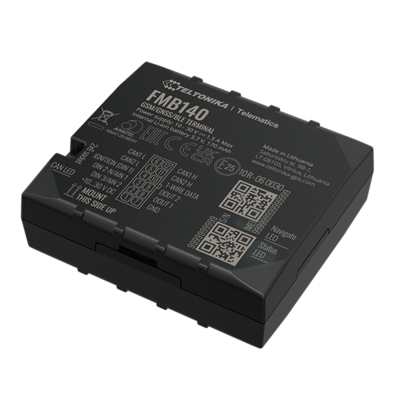
GNSS/GSM/Bluetooth® tracker with integrated CAN chip, internal GNSS/GSM antennas and internal battery
How to insert Micro-SIM card
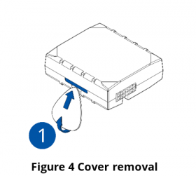
- Gently remove FMB140 cover using plastic pry tool from both sides.
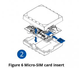
- Insert Micro-SIM card as shown with PIN request disabled or read Security info how to enter it later in Configurator. Make sure that Micro-SIM card cut-off corner is pointing forward to slot.
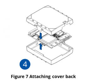
- Attach device cover back.
- Device is ready to be connected.
 |
Micro-SIM card insertion/removal must be performed when device is powered off – external voltage and internal battery disconnected. Otherwise Micro-SIM card might be damaged or device will not detect it. |
Battery placement after complete device disassembling
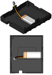
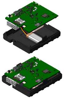
- Using double sided tape, stick internal battery to the bottom part of the device case. Battery should be glued approximately 15 millimeters from the bottom wall of the case. Picture on the left.
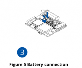
- Connect battery to the PCB.
- Gently place PCB into the bottom case.
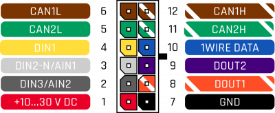
2x6 socket pinout
Mounting recommendations
- Connecting wires
- Wires should be connected while the module is not plugged in.
- Wires should be fastened to stable wires or other non-moving parts. Any heat emitting and/or moving objects should be kept away from the wires.
- There should be no exposed wires. If factory isolation was removed while connecting wires, the isolation material should be applied.
- If the wires are placed in the exterior or in places where they can be damaged or exposed to heat, humidity, dirt, etc., additional isolation should be applied and the wires should not be loose.
- Wires cannot be connected to the board computers or control units.
- Connecting power source
- Be sure that after the car computer goes to sleep mode, power might be still available on the power wires. Depending on car, this may happen in 5 to 30 minutes period.
- When module is connected, measure voltage again to make sure it did not decrease.
- It is recommended to connect to the main power cable in the fuse box.
- 3 A, 125 V external fuse shall be used.
- Connecting ignition wire
- Be sure to check if it is a real ignition wire i. e. power does not disappear after starting the engine.
- Check if this is not an ACC wire (when key is in the first position, most of the vehicle electronics are available).
- Check if power is still available when you turn off any of vehicles devices.
- Ignition is connected to the ignition relay output. As alternative, any other relay, which has power output when ignition is on, may be chosen.
- Connecting ground wire
- Ground wire is connected to the vehicle frame or metal parts that are fixed to the frame.
- If the wire is fixed with the bolt, the loop must be connected to the end of the wire.
- For better contact scrub paint from the spot where loop is going to be connected.
 |
PAY ATTENTION! Connecting the power supply must be carried out in a very low impedance point of on-board vehicle network. These points in the car are the battery terminals. Therefore, we recommend connecting the power of FMB140 (GND and POWER wires) directly to the battery terminals. Another valid option is to connect the wires to the main POWER cable inside the fuse box (if there is none, then to the power supply where the fuses of vehicle’s computer are), GND wire must be connected in a special point, designed to connect GND vehicle computer. Connecting the GND at an arbitrary point to the mass of the car is unacceptable, as static and dynamic potentials on the line GND will be unpredictable, which can lead to unstable FMB140 operation and even its failure. |
Installation photos
FMB140 is the device that has internal GNSS and GSM antenna.
Device should be mounted with the sticker / engraving view to the open sky (metal free). FMB140 area with engraving is shown in figure below:

FMB140 can be mounted under the plastic panel behind the front window, with the sticker / engraving direction to a window (sky). It is recommended to place FMB1YX behind dashboard as close to the window as possible. A good example of GNSS antenna placement is displayed in a picture below (area colored blue).
SIM card should be inserted in the module while the connector is plugged off (while module has no power).
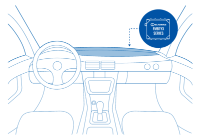
Safety information
This message contains information on how to operate FMB140 safely. By following these requirements and recommendations, you will avoid dangerous situations. You must read these instructions carefully and follow them strictly before operating the device!
- The device uses SELV limited power source. The nominal voltage is +12 V DC. The allowed voltage range is +10..+30V DC.
- To avoid mechanical damage, it is advised to transport the device in an impact-proof package. Before usage, the device should be placed so that its LED indicators are visible. They show the status of device operation.
- When connecting the 2x6 connector wires to the vehicle, the appropriate jumpers of the vehicle power supply should be disconnected.
- Before unmounting the device from the vehicle, the 2x6 connector must be disconnected.
- The device is designed to be mounted in a zone of limited access, which is inaccessible to the operator. All related devices must meet the requirements of EN 60950-1 standard.
- The device FMB140 is not designed as a navigational device for boats.
Precautions

