Template:Gyroscope features: Difference between revisions
| (6 intermediate revisions by 2 users not shown) | |||
| Line 21: | Line 21: | ||
* '''Continuous Monitoring''': With a high Output Data Rate (ODR) of up to 400 Hz, gyroscopes can record detailed motion changes, making them indispensable in crash detection, eco/green driving analysis, and advanced vehicle telematics systems.}}} | * '''Continuous Monitoring''': With a high Output Data Rate (ODR) of up to 400 Hz, gyroscopes can record detailed motion changes, making them indispensable in crash detection, eco/green driving analysis, and advanced vehicle telematics systems.}}} | ||
=== Features | === Features that utilize Gyroscope=== | ||
{{{features|The integration of gyroscopes into firmware introduces a suite of advanced functionalities, significantly enhancing motion tracking and data analysis capabilities. Key features include: | {{{features|The integration of gyroscopes into firmware introduces a suite of advanced functionalities, significantly enhancing motion tracking and data analysis capabilities. Key features include: | ||
| Line 27: | Line 27: | ||
* '''High-Resolution Data Collection''': The IMU ODR has been increased to 400 Hz, providing double the sampling rate of earlier implementations This ensures even the shortest movements are captured with high accuracy, benefiting crash detection and eco/green driving analytics. | * '''High-Resolution Data Collection''': The IMU ODR has been increased to 400 Hz, providing double the sampling rate of earlier implementations This ensures even the shortest movements are captured with high accuracy, benefiting crash detection and eco/green driving analytics. | ||
* '''Crash Trace Enhancements''': Separate configurable durations for capturing data before and after crash events (up to a combined total of 20 seconds before + after crash event) allow for detailed reconstructions. These additionally include gyroscopic data on axis rotations. | * '''Crash Trace Enhancements''': Separate configurable durations for capturing data before and after crash events (up to a combined total of 20 seconds before + after crash event) allow for detailed reconstructions. These additionally include gyroscopic data on axis rotations. | ||
* '''Eco-Driving Scenario Improvements''': By integrating gyroscope data, new parameter -"Total Angle Changed" during driving events allow for granular analysis of driver behavior, helping fleet managers optimize performance and safety. | * '''Eco-Driving Scenario Improvements''': By integrating gyroscope data, new parameter -'''"Total Angle Changed"''' during driving events allow for granular analysis of driver behavior, helping fleet managers optimize performance and safety.<br> | ||
This feature can be enabled, only when: | |||
#Eco/Green driving feature is '''enabled''' | |||
#Source is set as '''Accelerometer''' | |||
#Advanced Eco Driving is '''enabled''' | |||
# Eco driving total angle changes is '''enabled''' | |||
[[File:Total angle changed v2.png|none]] | |||
* '''Advanced Vehicle Stability Monitoring''': For applications like heavy machinery or agriculture, gyroscopes monitor roll and pitch angles to ensure safe and stable operation.}}} | * '''Advanced Vehicle Stability Monitoring''': For applications like heavy machinery or agriculture, gyroscopes monitor roll and pitch angles to ensure safe and stable operation.}}} | ||
| Line 171: | Line 178: | ||
===Crash trace format explanation=== | ===Crash trace format explanation=== | ||
When enabled with configuration, gyroscope data is enabled in the crash trace. Special record | When enabled with configuration, gyroscope data is enabled in the crash trace. Special record with '''AVL ID 1422''' is used instead of standard crash trace AVL ID 259. Records generated after the crash will include standard data and trace data sent with these AVL IDs: | ||
{| class="nd-othertables_2" style="width:100%;" | {| class="nd-othertables_2" style="width:100%;" | ||
|+ | |+ | ||
| Line 200: | Line 207: | ||
| style="vertical-align: middle;" |Specialized data collection during crash events. | | style="vertical-align: middle;" |Specialized data collection during crash events. | ||
|- | |- | ||
! colspan="6" style="text-align: left;" |Data Structure | ! colspan="6" style="text-align: left;" |AVL ID 1422 Data Structure | ||
|- | |- | ||
| style="vertical-align: middle; text-align: center;" |- | | style="vertical-align: middle; text-align: center;" |- | ||
| Line 281: | Line 288: | ||
|} | |} | ||
These devices must be equipped with gyroscope | These devices must be equipped with gyroscope supported hardware. Clients with older models will require hardware upgrades to access this functionality. Note that gyroscope features are not available as a firmware-only update. | ||
Latest revision as of 15:10, 3 December 2024
Introduction
This page provides an in-depth exploration of the gyroscope feature and its integration into the firmware for supported devices. It highlights the technological advancements offered by gyroscopes, including their ability to measure and process both linear and rotational motion. The implementation of gyroscopes into firmware enhances crash detection, eco-driving scenarios, and driver behavior monitoring, providing detailed data critical for various industries such as insurance, transportation, agriculture, and heavy machinery. This page aims to provide comprehensive insights into the feature's functionality, configuration, and real-world applications.
What is a Gyroscope?
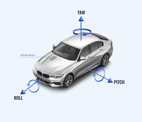
A gyroscope is a device that measures angular velocity, or the rate of rotation, around three perpendicular axes: Roll, Pitch, and Yaw. These measurements, expressed in degrees per second (or radians per second), enable the tracking of rotational motion in three-dimensional space. When paired with a 3-axis accelerometer, the combination forms a 6-axis inertial measurement unit (IMU), capable of capturing both linear and rotational movement.


Gyroscopes are essential for applications requiring precise motion detection and orientation tracking. For example:
- Rotation and Orientation: Gyroscopes detect rotational movements, providing data for scenarios involving vehicle spins, rolls, or tilts.
- Crash Analysis: By integrating linear acceleration data (from accelerometers) with rotational data, gyroscopes enable a comprehensive understanding of crash mechanics, capturing the angle and orientation of a vehicle during impact.
- Continuous Monitoring: With a high Output Data Rate (ODR) of up to 400 Hz, gyroscopes can record detailed motion changes, making them indispensable in crash detection, eco/green driving analysis, and advanced vehicle telematics systems.
Features that utilize Gyroscope
The integration of gyroscopes into firmware introduces a suite of advanced functionalities, significantly enhancing motion tracking and data analysis capabilities. Key features include:
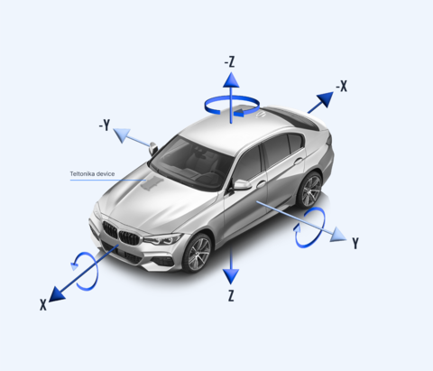
- 6-Axis Motion Tracking: The gyroscope combines rotational data (Roll, Pitch, Yaw) with linear data (X, Y, Z) from the accelerometer, both gyroscope and accelerometer data is available as I/O parameters: Roll , Pitch, Yaw and Axis X, Axis Y, Axis Z respectively.
- High-Resolution Data Collection: The IMU ODR has been increased to 400 Hz, providing double the sampling rate of earlier implementations This ensures even the shortest movements are captured with high accuracy, benefiting crash detection and eco/green driving analytics.
- Crash Trace Enhancements: Separate configurable durations for capturing data before and after crash events (up to a combined total of 20 seconds before + after crash event) allow for detailed reconstructions. These additionally include gyroscopic data on axis rotations.
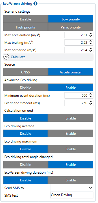
- Eco-Driving Scenario Improvements: By integrating gyroscope data, new parameter -"Total Angle Changed" during driving events allow for granular analysis of driver behavior, helping fleet managers optimize performance and safety.
This feature can be enabled, only when:
- Eco/Green driving feature is enabled
- Source is set as Accelerometer
- Advanced Eco Driving is enabled
- Eco driving total angle changes is enabled

- Advanced Vehicle Stability Monitoring: For applications like heavy machinery or agriculture, gyroscopes monitor roll and pitch angles to ensure safe and stable operation.
Configuration Parameters
The gyroscope feature comes with several configurable parameters, enabling users to tailor its functionality to specific needs. Below is a detailed table:
| Parameter ID | Parameter Name | Value Range | Default Value | Description | |
|---|---|---|---|---|---|
| Min | Max | ||||
| 11009 | Eco Driving Total Angle Changed | 0 | 1 | 0 | Total angle changed (degrees) on all axis during event |
| 78100 | IMU Crash Trace Duration Before | 2 | 18 | 9 | Crash trace duration before the event in seconds (s). |
| 78101 | IMU Crash Trace Duration After | 2 | 18 | 5 | Crash trace duration after the event in seconds (s). |
| 78112 | Gyro in Crash Trace | 0 | 1 | 0 | Enable gyroscope data in crash trace. |
AVL ID List
| AVL ID | Parameter Name | Bytes | Type | Value Range | Multiplier | Units | Description | |
|---|---|---|---|---|---|---|---|---|
| Min | Max | |||||||
| 1419 | Roll | 2 | Signed | -2500 | 2500 | 0.1 | dps | Real-time gyroscope X-axis rotational data. |
| 1420 | Pitch | 2 | Signed | -2500 | 2500 | 0.1 | dps | Real-time gyroscope Y-axis rotational data. |
| 1421 | Yaw | 2 | Signed | -2500 | 2500 | 0.1 | dps | Real-time gyroscope Z-axis rotational data. |
| 1422 | Accelerometer + Gyro Crash Trace | Variable | Stream | - | - | N/A | - | Stream of accelerometer and gyroscope data during crash events. |
| 1330 | Crash Trace ODR | 2 | Unsigned | 20 | 400 | N/A | Hz | Configured output data rate for crash trace. |
| 1170 | IMU Crash Trace Duration Before | 1 | Unsigned | 2 | 18 | N/A | s | Time in seconds for IMU crash trace data recorded before the event. |
| 1171 | IMU Crash Trace Duration After | 1 | Unsigned | 2 | 18 | N/A | s | Time in seconds for IMU crash trace data recorded after the event. |
| 1172 | GNSS Trace Duration | 1 | Unsigned | 0 | 30 | N/A | s | Configured GNSS trace duration for crash events. |
Crash trace format explanation
When enabled with configuration, gyroscope data is enabled in the crash trace. Special record with AVL ID 1422 is used instead of standard crash trace AVL ID 259. Records generated after the crash will include standard data and trace data sent with these AVL IDs:
| AVL ID | Element Name | Element Size | Type | Description | ||
|---|---|---|---|---|---|---|
| Details | Axis Information | Usage | ||||
| 247 | Crash Event | Uint8 | 1 Byte | Indicates the occurrence of a crash event. | Not applicable | Triggered during crash detection. |
| 1422 | Trace Data | Variable | Stream | Includes accelerometer and gyroscope data for crash analysis. | Axis X, Axis Y, Axis Z, Roll, Pitch, Yaw | Specialized data collection during crash events. |
| AVL ID 1422 Data Structure | ||||||
| - | Axis X | Int16 | 2 Bytes | X-axis angular data from gyroscope. | Measured during crash event. | |
| - | Axis Y | Int16 | 2 Bytes | Y-axis angular data from gyroscope. | Measured during crash event. | |
| - | Axis Z | Int16 | 2 Bytes | Z-axis angular data from gyroscope. | Measured during crash event. | |
| - | Roll | Int16 | 2 Bytes | Roll angular rate data. | Measured during crash event. | |
| - | Pitch | Int16 | 2 Bytes | Pitch angular rate data. | Measured during crash event. | |
| - | Yaw | Int16 | 2 Bytes | Yaw angular rate data. | Measured during crash event. | |
Use Cases
The gyroscope feature unlocks several practical applications, addressing needs across diverse industries:
- Crash Event Reconstruction: By combining linear and rotational data, gyroscopes provide a detailed account of vehicle dynamics during crashes. This includes capturing rollovers, skids, and impact angles, offering unparalleled insights for insurance claims and accident analysis.
- Driver Behavior Monitoring: Fleet managers can use gyroscope data to detect unsafe driving behaviors such as sharp cornering, drifting, or harsh braking, promoting safer driving practices.
- Predictive Maintenance: Rotational data helps identify tire wear and suspension issues by tracking how vehicles handle during aggressive maneuvers, enabling preemptive repairs.
Industry-Specific Applications:
- Insurance Telematics: Ensures accurate crash reconstructions with combined accelerometer and gyroscope data.
- Heavy Machinery: Tracks machinery stability in hazardous environments, reducing risks of rollovers or tipping.
- Rental and Leasing: Detects improper usage or reckless driving, minimizing wear and tear on vehicles.
- Agriculture: Helps maintain consistent angles during tasks like plowing, spraying, or planting, enhancing precision and efficiency.
Supported Devices
Devices that can be equipped with gyroscope and are compatible with gyroscope functionality:
- FMT100
- FMC880
- FMM880
Latest Firmware with gyroscope support:
| DEVICE | DEVICE LAUNCH DATE | FIRMWARE RELEASE TO FACTORY DATE | FIRMWARE VERSION ERRATA | CONFIGURATOR VERSION ERRATA | DOWNLOAD |
|---|---|---|---|---|---|
| FMT100 FMC880 FMM880 | 2024-12 | 2024-12 | 03.30.00.Rev.112 | 1.8.4_E.GYRO_R.2 |
These devices must be equipped with gyroscope supported hardware. Clients with older models will require hardware upgrades to access this functionality. Note that gyroscope features are not available as a firmware-only update.
