FTC881 First Start: Difference between revisions
No edit summary |
Replaced content with "{{Template:FTX First Start|model=FTC881}}" Tag: Replaced |
||
| (4 intermediate revisions by 3 users not shown) | |||
| Line 1: | Line 1: | ||
{{Template:FTX First Start|model=FTC881}} | |||
= | |||
Latest revision as of 15:18, 8 May 2025
Main Page > Fast & Easy Trackers > FTC881 > FTC881 First StartNext-generation high voltage 4G LTE Cat 1 battery-mounted vehicle GPS tracker with enhanced GNSS accuracy and IP69K resistance.

KNOW YOUR DEVICE

SET UP YOUR DEVICE
 |
Physical SIM card insertion/removal must be performed when device is powered off – external voltage disconnected. Otherwise, the SIM card might be damaged or device will not detect it. |

HOW TO REMOVE COVER
| |
Device casing is designed to be water-proof and match requirements for IP69K. Please note that once the cover is fully clipped it will require additional plastic pry tools to be opened! Please make sure to review short walkthrough video for more details: |
PINOUT
| PIN NUMBER | PIN NAME | DESCRIPTION |
 |
|---|---|---|---|
| 1 | VCC | (Red) Power supply (+10-90 V DC) (+). | |
| 2 | GND | (Black) Ground (-). |
PC CONNECTION (WINDOWS)
- Power-up FTC881 with DC voltage (10-90V) power supply using power wires. LEDs should start blinking, see "LED BEHAVIOUR DESCRIPTION".
- Connect device to computer using USB Type-C cable and install USB driver, see "HOW TO INSTALL USB DRIVERS (WINDOWS)".
HOW TO INSTALL USB DRIVERS (WINDOWS)
- Please download COM port drivers from here.
- Extract and run TeltonikaCOMDriver.exe.
- Click Next in driver installation window.
- In the following window click Install button.
- Setup will continue installing the driver and eventually the confirmation window will appear. Click Finish to complete the setup.
CONFIGURATION (WINDOWS)
Most Teltonika devices are shipped with default factory settings. Use Telematics Configuration Tool (TCT) to change these settings according to your needs.
| TCT | |
|---|---|
| Operating system | Windows 10 Windows 11 |
| MS .NET Framework version | MS .NET framework 6.0 |
| Version | 64 bit |
| Disk Storage | 1 GB of free disk space |
| Internet | Ethernet port or Wi-Fi w/ network access for auto-update |
TCT
- Download the TCT (compressed archive).
- Extract the archive and launch the executable. The TCT will be installed.
- Launch the TCT.
- In the Discovered devices list, select your device and press Configure.
- The Device status window opens. It contains device, GNSS and Cellular information.

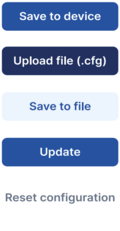


Save to device – saves configuration to device.
Upload file – loads configuration from file.
Save to file – saves configuration to file.
Update – update device firmware.
Reset configuration – sets device configuration to default.
Most important configuration sections are Mobile network (Server, Mobile network settings) and Tracking settings (data collection parameters). More details about FTC881 configuration using TCT can be found here.
QUICK SMS CONFIGURATION
The default configuration ensures best track quality and optimal data usage.
Quickly set up your device by sending this SMS command to it:

DEFAULT CONFIGURATION SETTINGS

After successful SMS configuration, FTC881 device will synchronize time and update records to configured server. Time intervals and default I/O elements can be changed by using TCT or Parameter list.
MOUNTING RECOMMENDATIONS
DEVICE FASTENING
- Locate the battery in your vehicle. If present remove the battery cover to access the battery.
- There is a double sided tape on the back of the device, use it to attach the device on the battery, so that the GNSS antenna and LEDs indicators are facing up.
CONNECTING POWER SOURCE
- Device power wire is designed to be directly connected to the positive terminal fastener of the vehicle battery.
CONNECTING GROUND WIRE
- Device ground wire is designed to be directly connected to the negative terminal fastener of the vehicle battery.
LED INDICATIONS
This section is an explanation of LED indications on FTC881 device.
NAVIGATION LED INDICATIONS
| Behaviour | Meaning |
|---|---|
| Blinking every second | GNSS module is working, GNSS fix is acquired (normal operation) |
| Permanently switched on | GNSS module is working, but fix is not acquired (no position) |
| Off | GNSS module is off because: (a) the device is not working or (b) the device is in sleep mode |
STATUS LED INDICATIONS
| Behaviour | Meaning |
|---|---|
| Blinking every second | Device is working, GPRS session is active (normal operation) |
| On | Device is working, no active GPRS sessions |
| Off | Device is not working |
BASIC CHARACTERISTICS
| Module | |
|---|---|
| Name | FTC881-QJAB0: Quectel EG915U-EU with AG3335
|
| Technology | LTE CAT 1/GSM/GPRS/GNSS |
| GNSS | |
| GNSS | GPS, GLONASS, GALILEO, BEIDOU |
| Receiver | L1: 75 channel |
| Tracking sensitivity | -165 dBm |
| Position Accuracy | < 1.5 m CEP |
| Velocity Accuracy | < 0.1 m/s (within +/- 15% error) |
| Hot start | < 1 s |
| Warm start | < 25 s |
| Cold start | < 35 s |
| Cellular | |
| Technology | LTE CAT 1/GSM |
| 2G bands | FTC881-QJAB0: GSM: B2/B3/B5/B8 |
| 4G bands | FTC881-QJAB0: LTE FDD (CAT 1): B1/B3/B5/B7/B8/B20/B28 |
| Data transfer | LTE FDD (CAT 1): Max. 10 Mbps (DL) / Max. 5 Mbps (UL) GSM (GPRS): Max. 85.6 Kbps (DL) / Max. 85.6 Kbps (UL) |
| Transmit power | Class 5 for GSM850/900: 30±5dBM Class 3 for GSM1800/1900: 29±5dBM Class 3 for LTE-FDD: 26±5dBM |
| Data support | SMS (TEXT, PDU), Network protocols (TCP, UDP) |
| Power | |
| Input voltage range | 10 - 90 V DC |
| Back-up battery | 320 mAh Li-Ion battery 3.7V (1.18 Wh) |
| Internal fuse | 3A, 125V |
| Power Consumption | TBA |
| Interface | |
| Connection | U-Type cable |
| GNSS antenna | Internal High Gain |
| GSM antenna | Internal High Gain |
| USB | 2.0 USB Type-C |
| LED indication | 2 status LED lights |
| SIM | Nano-SIM |
| Memory | 128MB internal flash memory |
| Physical Specification | |
| Dimensions | 118 x 48 x 18.5 mm (L x W x H) |
| Weight | 118 g |
| Operating Environment | |
| Operating temperature | -30 °C to +85 °C |
| Storage temperature | -30 °C to +85 °C |
| Operating humidity | 5% to 95% non-condensing |
| Ingress protection rating | IP69K |
| Battery charge temperature | 0 °C to +45 °C |
| Battery discharge temperature | -20 °C to +60 °C |
| Battery storage conditions | -10 °C to +50 °C for 1 month -10 °C to +35 °C for 3 months 0 °C to +30 °C for 1 year |
| Data Codec | |
| Codec support | Codec 8 Extended |
| Features | |
| Sensors | Accelerometer |
| Scenarios | Crash Detection, Over Speeding detection, Trip, Odometer, Eco driving, Excesive idling, Network jamming detection, Unplug detection, Auto Geofence, Towing detection, Static navigation, Custom Scenarios |
| Sleep modes | Online sleep, Deep sleep, Power off sleep |
| Configuration and firmware update | FOTA WEB, Telematics Configuration Tool (TCT) |
| SMS | Configuration, DOUT control, Debug |
| GPRS commands | Configuration, DOUT control, Debug |
| Time Synchronization | GNSS, NTP, NITZ |
| Ignition detection | Accelerometer, External Power Voltage |