Jump to content

1-Wire RFID Reader: Difference between revisions

From Teltonika Telematics Wiki
m Decoding RFID Card ID: Improved word choice
[GTPGTM-10943]
 
(One intermediate revision by the same user not shown)
Line 1: Line 1:
==Introduction to the product==
{{Template:1-Wire Accessory|accessory=RFID}}
 
 
'''Description:'''
 
One of the implemented features for fleet management devices is 1-Wire data protocol, which can be used to read RFID Tags by emulating them using iButton protocols. It is a convenient way to implement driver authorization in your vehicles if you want to use RFID Tags with minimal setup complexity.
 
'''1-Wire RFID readers are great in these use cases:'''
 
*Immobilizer - prevent anyone from starting the vehicle without scanning an iButton first.
*Authorized driving - keep track of who is driving your vehicle according to the iButton ID they use to authenticate themselves.
*AutoGeofencing – gives ability to know when car leaves customized areas without iButton authorization.
<br>
[[File:RFID_Reader.jpg|alt=|right|400x400px]]
 
 
<br>


==Product Specification==
 
{| class="wikitable"
|+
! style="width:30%; border: 1px solid white; border-bottom: 2px solid #0054A6; background: white; color: #0054A6; text-align: left;" |NAME
! style="border: 1px solid white; border-bottom: 2px solid #0054A6; background: white; color: #0054A6; text-align: left;" |DESCRIPTION
|-
| style="border: 1px solid white; border-bottom: 2px solid #E8E8E8; text-align: left; vertical-align: center; background: white;" |Interface
| style="border: 1px solid white; border-bottom: 2px solid #E8E8E8; text-align: left; vertical-align: center; background: white;" |1-Wire Interface
|-
| style="border: 1px solid white; border-bottom: 2px solid #E8E8E8; text-align: left; vertical-align: center; background: white;" |Wiring
| style="border: 1px solid white; border-bottom: 2px solid #E8E8E8; text-align: left; vertical-align: center; background: white;" |White wire – 1-wire data, Brown wire – power supply, Green - ground.
|-
| style="border: 1px solid white; border-bottom: 2px solid #E8E8E8; text-align: left; vertical-align: center; background: white;" |Power Supply
| style="border: 1px solid white; border-bottom: 2px solid #E8E8E8; text-align: left; vertical-align: center; background: white;" |6,5-30 V DC
|-
| style="border: 1px solid white; border-bottom: 2px solid #E8E8E8; text-align: left; vertical-align: center; background: white;" |Frequency standard
| style="border: 1px solid white; border-bottom: 2px solid #E8E8E8; text-align: left; vertical-align: center; background: white;" |125 kHz
|-
| style="border: 1px solid white; border-bottom: 2px solid #E8E8E8; text-align: left; vertical-align: center; background: white;" |Type of transponder
| style="border: 1px solid white; border-bottom: 2px solid #E8E8E8; text-align: left; vertical-align: center; background: white;" |Manchester, 64 cycles per bit
|-
| style="border: 1px solid white; border-bottom: 2px solid #E8E8E8; text-align: left; vertical-align: center; background: white;" |Antenna surface area
| style="border: 1px solid white; border-bottom: 2px solid #E8E8E8; text-align: left; vertical-align: center; background: white;" |6,8 cm²
|-
| style="border: 1px solid white; border-bottom: 2px solid #E8E8E8; text-align: left; vertical-align: center; background: white;" |Reading range
| style="border: 1px solid white; border-bottom: 2px solid #E8E8E8; text-align: left; vertical-align: center; background: white;" |4 cm
|-
| style="border: 1px solid white; border-bottom: 2px solid #E8E8E8; text-align: left; vertical-align: center; background: white;" |Reading frequency
| style="border: 1px solid white; border-bottom: 2px solid #E8E8E8; text-align: left; vertical-align: center; background: white;" |6 times per second for identification, 2 times per second when transponder is in range of reader
|-
| style="border: 1px solid white; border-bottom: 2px solid #E8E8E8; text-align: left; vertical-align: center; background: white;" |Supported 1-Wire commands
| style="border: 1px solid white; border-bottom: 2px solid #E8E8E8; text-align: left; vertical-align: center; background: white;" |0x33 (0x0F) - Read ROM, 0xF0 - Search ROM
|-
| style="border: 1px solid white; border-bottom: 2px solid #E8E8E8; text-align: left; vertical-align: center; background: white;" |Fastening method
| style="border: 1px solid white; border-bottom: 2px solid #E8E8E8; text-align: left; vertical-align: center; background: white;" |M12 thread
|-
| style="border: 1px solid white; border-bottom: 2px solid #E8E8E8; text-align: left; vertical-align: center; background: white;" |Cable length
| style="border: 1px solid white; border-bottom: 2px solid #E8E8E8; text-align: left; vertical-align: center; background: white;" |40 cm
|-
| style="border: 1px solid white; border-bottom: 2px solid #E8E8E8; text-align: left; vertical-align: center; background: white;" |Operating temperature
| style="border: 1px solid white; border-bottom: 2px solid #E8E8E8; text-align: left; vertical-align: center; background: white;" |-20 ºC to +55 ºC
|-
| style="border: 1px solid white; border-bottom: 2px solid #E8E8E8; text-align: left; vertical-align: center; background: white;" |Operating humidity
| style="border: 1px solid white; border-bottom: 2px solid #E8E8E8; text-align: left; vertical-align: center; background: white;" |Up to 70%
|-
| style="border: 1px solid white; border-bottom: 2px solid #E8E8E8; text-align: left; vertical-align: center; background: white;" |Supported by
| style="border: 1px solid white; border-bottom: 2px solid #E8E8E8; text-align: left; vertical-align: center; background: white;" |<span class="mw-collapsible mw-collapsed"> [https://wiki.teltonika-gps.com/view/FMB110 FMB110], [https://wiki.teltonika-gps.com/view/FMB120 FMB120], [https://wiki.teltonika-gps.com/view/FMB122 FMB122], [https://wiki.teltonika-gps.com/view/FMB125 FMB125], [https://wiki.teltonika-gps.com/view/FMU125 FMU125], [https://wiki.teltonika-gps.com/view/FMM125 FMM125], [https://wiki.teltonika-gps.com/view/FMC125 FMC125], [https://wiki.teltonika-gps.com/view/FMB130 FMB130], [https://wiki.teltonika-gps.com/view/FMU130 FMU130], [https://wiki.teltonika-gps.com/view/FMC130 FMC130], [https://wiki.teltonika-gps.com/view/FMM130 FMM130], [https://wiki.teltonika-gps.com/view/FMB140 FMB140], [https://wiki.teltonika-gps.com/view/FMB202 FMB202], [https://wiki.teltonika-gps.com/view/FMB204 FMB204], [https://wiki.teltonika-gps.com/view/FMB640 FMB640], [https://wiki.teltonika-gps.com/view/FMC640 FMC640], [https://wiki.teltonika-gps.com/view/FMM640 FMM640] </span>
|-
|}
 
==Installation==
To connect the 1-wire RFID reader, simply connect the 1-Wire Signal wire from the reader to the 1-Wire Data pin on the device, connect the 1-Wire Power wire to the VCC and connect the ground wire to the same grounding used for the device.
<br>
<br>
[[File:RFID connection2.png|alt=|center|thumb|682x682px|Relay is optional, driver authentication can work only with RFID]]
<br>
{| class="wikitable"
|+
! style="width:10%; border: 1px solid white; border-bottom: 2px solid #0054A6; background: white; color: #0054A6; text-align: left;" |PIN NUMBER
! style="width:15%; border: 1px solid white; border-bottom: 2px solid #0054A6; background: white; color: #0054A6; text-align: left;" |PIN NAME
! style="width:25%; border: 1px solid white; border-bottom: 2px solid #0054A6; background: white; color: #0054A6; text-align: left;" |
DESCRIPTION
|-
| style="border: 1px solid white; border-bottom: 2px solid #E8E8E8; text-align: left; vertical-align: center; background: white;" |1
| style="border: 1px solid white; border-bottom: 2px solid #E8E8E8; text-align: left; vertical-align: center; background: white;" |<span style="color:#00B000">'''1-wire Data (Data Dallas)'''</span>
| style="border: 1px solid white; border-bottom: 2px solid #E8E8E8; text-align: left; vertical-align: center; background: white;" |Outputs identification data via 1-Wire interface
|-
| style="border: 1px solid white; border-bottom: 2px solid #E8E8E8; text-align: left; vertical-align: center; background: white;" |2
| style="border: 1px solid white; border-bottom: 2px solid #E8E8E8; text-align: left; vertical-align: center; background: white;" |<span style="color:#FF0000">'''VCC''' (+)</span>
| style="border: 1px solid white; border-bottom: 2px solid #E8E8E8; text-align: left; vertical-align: center; background: white;" |Power supply for the sensor (6,5-30 V DC)
|-
|-
| style="border: 1px solid white; border-bottom: 2px solid #E8E8E8; text-align: left; vertical-align: center; background: white;" |3
| style="border: 1px solid white; border-bottom: 2px solid #E8E8E8; text-align: left; vertical-align: center; background: white;" |<span style="color:#000000">'''GND''' </span>(-)
| style="border: 1px solid white; border-bottom: 2px solid #E8E8E8; text-align: left; vertical-align: center; background: white;" |Ground
|}
 
<br />
 
''Note: this describes the installation of [https://teltonika-gps.com/product/rfid-reader/ 1-Wire reader] supplied by Teltonika, other manufacturer readers may have different wiring may be powered via 1-Wire and etc.''
 
<br>
 
==Device configuration==
Since this reader emulates received RFID values as iButton values, it has identical functionality as the iButton reader in this regard. The reader works as soon as it is connected, but the iButton isn't used anywhere other than displayed in the iButton I/O element. In order to use it for the Immobilizer scenario, the device must have the scenario enabled. Then, iButton check can be enabled to only accept iButtons specified in the iButton list under the 1-Wire tab. <br><br>[[File:IButtonReaderConfig.png|border|frameless|682x682px]]
 
[[File:Io_1wire_temp2.png|frameless|682x682px]]
 
<br>
 
==Decoding RFID Card ID==
RFID Card ID should be entered into the iButton List correctly to make this feature work correctly. Please refer to the guide below on how to enter an RFID Card ID.
 
1. RFID Card Reader should be connected to the device according to the [https://wiki.teltonika-gps.com/view/1-Wire_RFID_Reader#Installation/ wiring scheme]. <br>
2. The device should be connected to the PC, and the Teltonika Configurator should be opened. <br>
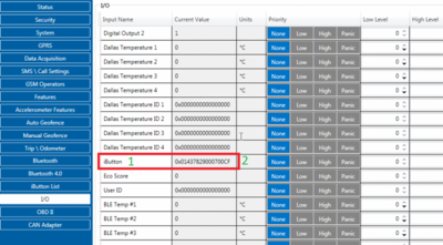
3. Open the "I/O" tab and find the iButton parameter in the list (ID 50390). <br>
4. Attach the RFID card to the reader. The value in the configurator should change. <br> [[File:IButton_ID_detection.png|border|frameless|500x500px]]<br>
5. In this example iButton value is 01437829000700CF. The value should be converted to the format compatible with the Authorization List according to the figure below: [[File:iButton_ID_decoding.png|border|frameless|400x400px]]<br>
6. Converted value (CF00070029784301) can be entered into the Authorization List. <br><br>
'''NOTE:''' On FMX6 project devices, it works differently.
There is no need to make any changes whenever entering/receiving the iButton/RFID value
 
[[Category:Accessories]]
[[Category:Accessories]]

Latest revision as of 13:52, 30 January 2026

Main Page > Accessories > 1-Wire RFID Reader

Introduction

1-Wire data protocol, implemented in many Teltonika devices, can be used to read RFID tags (by emulating them using iButton protocols).

1-Wire RFID readers are a convenient way to implement driver authorization and other functionalities.

Use cases:

  • Immobilizer - prevent the starting of a vehicle without first scanning an RFID tag.
  • Authorized driving - keep track of who is driving the vehicle according to the RFID tag they use to authenticate themselves.
  • Auto Geofencing - get notified when a vehicle leaves a pre-defined area without authorization.


Specifications

NAME DESCRIPTION
Interface 1-Wire
Wiring White = 1-wire data, Brown = Power supply, Green = Ground.
Power Supply 6.5-30 VDC
Frequency standard 125 kHz
Type of transponder Manchester, 64 cycles per bit
Antenna surface area 6,8 cm²
Reading range 4 cm
Reading frequency 6 times per second for identification, 2 times per second when transponder is in range of reader
Supported 1-Wire commands 0x33 (0x0F) - Read ROM, 0xF0 - Search ROM
Fastening method M12 thread
Cable length 40 cm
Operating temperature -20 ºC to +55 ºC
Operating humidity Up to 70%
Supported by FMB110, FMB120, FMB122, FMB125, FMU125, FMM125, FMC125, FMB130, FMU130, FMC130, FMM130, FMB140, FMB202, FMB204, FMB640, FMC640, FMM640

Installation

Note! This chapter describes the installation of an accessory supplied by Teltonika. Accessories from other manufacturers may require different steps.
To connect the accessory to your system:

  1. Connect the ground wire to the same grounding used for the device.
  2. Connect the 1-Wire Signal wire from the reader to the 1-Wire Data pin on the device.
  3. Connect the 1-Wire Power wire to the VCC.
Relay is optional, driver authentication can work only with RFID
PIN NAME DESCRIPTION
1 1-wire Data (Dallas Data) Sends iButton ID
2 VCC (+) Power supply for the sensor (6.5-30 VDC)
3 GND (-) Ground

Tracker Configuration

Because this RFID reader emulates the received RFID values as iButton values, in configuration software it has identical functionality as the iButton reader.

The reader works as soon as it is connected, but the iButton isn't used anywhere other than displayed in the iButton I/O element. In order to use it for the Immobilizer scenario, the device must have the scenario enabled. Then, iButton check can be enabled to only accept iButtons specified in the iButton list under the 1-Wire tab.

Converting IO values to IDs

This short guide explains how to convert the iButton value in "I/O" menu to an ID usable in the iButton list in "1-Wire" menu.

Note! For FMx6 trackers, you do not need to convert these values.

  1. Connect your 1-Wire accessory to the tracker according to the wiring scheme.
  2. Connect the tracker to a PC, run Teltonika Configurator.
  3. Open the "I/O" menu and find the "iButton" parameter.
  4. Scan the 1-Wire accessory on the reader. The value in Configurator will shortly change.
  5. Take the value (here: 01437829000700CF) and convert it using the method shown below - then you will be able to use it in the iButton List.

Excel algorithm (copy-paste to a sheet):

  1. Column names:
    1. A1-iButton I/O
    2. B1-Removed Ox string
    3. C1-Final ID
  2. Column values:
    1. A2=0x01437829000700CF
    2. B2==MID(A2; 3; LEN(A2) - 2)
    3. C2==MID(B2; 15; 2) & MID(B2; 13; 2) & MID(B2; 11; 2) & MID(B2; 9; 2) & MID(B2; 7; 2) & MID(B2; 5; 2) & MID(B2; 3; 2) & MID(B2; 1; 2)