TEST-X: Difference between revisions
No edit summary |
DR - TEST |
||
| Line 1: | Line 1: | ||
= | == Dead Reckoning == | ||
'''Dead Reckoning''' is a navigation technique used to estimate current position of vehicle , direction of movement, based on its previous position and known speed. It uses additional sensor data to correct the position received from GNSS receiver.<br> | |||
Usage of Dead Reckoning is essential in scenarios where GNSS signal is weak or unavailable, such as underground parking lots, tunnels or dense forests.<br> | |||
Key points to understand before utilizing the Dead Reckoning functionality: | |||
* | * Installation | ||
* | * Configuration | ||
* | * Alignment | ||
== | === <u>Prerequisites and Important Settings</u> === | ||
* Device mounting quality – Correct device mounting is critical for Dead Reckoning operation. Improper mounting may result in incorrect sensor data and unreliable Dead Reckoning performance. | |||
* Dead Reckoning alignment maintenance – If Dead Reckoning alignment parameters are no longer valid, send the DR_RESET command and perform calibration. | |||
* Electric and hybrid vehicles – For electric and hybrid vehicles, DIN1 should be used for movement detection to ensure correct Dead Reckoning operation. | |||
* Dead Reckoning is not supported for two‑wheeled vehicles (e.g., motorcycles, scooters). | |||
=== <u>Basic Operation</u> === | |||
''' | '''<u>Installation</u>'''<br> | ||
The device must be mounted firmly in the vehicle, with good visibility of the sky. Failure to ensure proper mounting will result in inability to calibrate the device or inaccurate position estimation. Following examples ensure that the GNSS antenna is facing towards the sky and there are no physical obstacles, like metal plates, wires, are blocking the GNSS signal. | |||
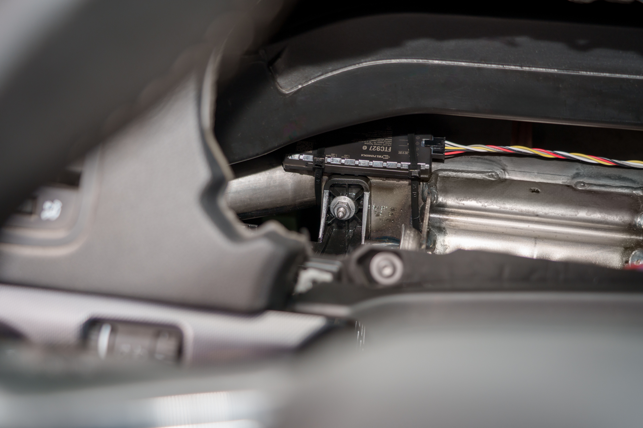
Good '''mounting''' examples ( <span style="color:red">'''If vehicle has a heated windshield, you should look for an alternative mounting location in the trunk, on some sturdy metal closer to backseat window'''</span>):<br> | |||
<div style="display: flex; flex-direction: row;"> | |||
[[File:FTC927 under the front dashboard in the middle of the car.jpg|thumb|left|280px|link=Special:Redirect/file/FTC927 under the front dashboard in the middle of the car.jpg|Dashboard in the middle of the car mount]] | |||
[[File:FTC927 beneath the speedometer panel.jpg|thumb|left|300px|link=Special:Redirect/file/FTC927 beneath the speedometer panel.jpg|Beneath the speedometer panel]] | |||
[[File:FTC927 above the glove box.jpg|thumb|left|300px|link=Special:Redirect/file/FTC927 above the glove box.jpg|Above glove box]] | |||
</div> | |||
== | Bad '''mounting''' examples:<br> | ||
<div style="display: flex; flex-direction: row;"> | |||
[[File:Dead Reckoning Unwanted movements will be detected by the IMU.png|thumb|left|280px|link=Special:Redirect/file/Dead Reckoning Unwanted movements will be detected by the IMU.png|Unwanted movements will be detected by the IMU]] | |||
[[File:Dead Reckoning Metal parts above the mount.png|thumb|left|300px|link=Special:Redirect/file/Dead Reckoning Metal parts above the mount.png|Metal parts above the mount]] | |||
[[File:Dead Reckoning vibration could cause unwanted device movements.png|thumb|left|300px|link=Special:Redirect/file/Dead Reckoning vibration could cause unwanted device movements.png|Places, where vibration could cause unwanted device movements]] | |||
</div> | |||
''' | '''<u>Configuration</u>'''<br> | ||
[[File:Dead Recknonig TCT panel_2.png|right|500px]] | |||
''The Dead Reckoning feature is configurable via the Dead Reckoning section in the GNSS settings group under System view in TCT.'' | |||
Parameter list can be found [[{{{model}}}_System#Parameter_list|here]]. | |||
===== Dead Reckoning alignment status ===== | |||
The Dead Reckoning alignment status is a 1-byte AVL ID (1433) that indicates the current status of the Dead Reckoning alignment. The possible values are:<br> | |||
*''' | * '''0''' - Unknown: Dead Reckoning status is unknown. | ||
*''' | * '''1''' - Init: Dead Reckoning alignment is initializing. | ||
*''' | * '''2''' - Coarse: Dead Reckoning is in alignment stage. | ||
* '''3''' - Stable: Dead Reckoning alignment stage has been completed. Estimation stage is in progress. | |||
* '''99''' - Standby: Dead Reckoning is in standby mode ('''NOTE''': this status is availabe with 3.7.X or newer firmware version) | |||
===== Turning alignment ===== | |||
The turning alignment is a 1-byte AVL ID ('''1434''') that indicates the current percentage of the turning alignment of the device. | |||
''' | ===== Straight alignment ===== | ||
The straight alignment is a 1-byte AVL ID ('''1435''') that indicates the current percentage of the straight alignment of the device. | |||
''' | |||
'''<u>Alignment</u>'''<br> | |||
Once device mounting adheres to the guidelines, alignment can be performed. The device '''must finish''' a specific alignment process to '''determine''' its mounting orientation. During this process, there are specific conditions that must be met: | |||
# The device must be '''stationary''' with clear sky visibility for at least 3 minutes. | |||
<!--# A great number of '''left and right''' turns must be performed.--> | |||
# Vehicle speed during alignment should be between 10 km/h and 100 km/h, with varying speeds preferred over extended constant-speed driving. | |||
# Avoid driving in underground tunnels or areas with poor GNSS signal, otherwise alignment needs to be restarted from the second step. | |||
[[File:Dead Reckoning TCT Swift .png|right|400px]] | |||
=== <u>Standby mode</u> === | |||
Standby Mode preserves Dead Reckoning calibration indefinitely, ensuring accurate position estimation after extended GNSS outages (e.g., a week in underground parking), and supports unlimited duration in this mode while maintaining full calibration integrity. | |||
Standby Mode has two behavior options: | |||
* '''Realignment''' – Calibration alignment is discarded after the Standby Timeout period. | |||
* '''Preserve alignment''' – Calibration alignment is retained during prolonged stationary periods. | |||
'''<u>Prerequisites and important Settings</u>'''<br> | |||
* If the device is remounted, send the DR_Reset SMS command and perform a full recalibration. This ensures all orientation- and sensor alignment parameters are refreshed, preventing inaccurate Dead Reckoning calculations after the installation change. | |||
'''<u>Basic Operation</u>'''<br> | |||
'''Entering Standby Mode''' | |||
*''' | The device can enter Standby Mode in two scenarios: | ||
* No movement detected | |||
If the device detects absence of movement, Dead Reckoning enters Standby Mode after the timeout defined by '''Standby timeout (ID 124)''' elapses. | |||
* Device enters sleep mode | |||
When the device transitions into sleep mode, the GNSS receiver is switched to power saving mode. | |||
Before GNSS powers down, Dead Reckoning enters Standby Mode '''immediately''', the scenario is paused, and the device proceeds into sleep mode. | |||
'''Exiting Standby Mode''' | |||
Standby Mode can be exited in the following cases: | |||
* Movement is detected | |||
When movement is detected, the device exits Standby Mode and resumes normal Dead Reckoning operation. If '''no movement is detected''', Dead Reckoning remains in Standby Mode. | |||
''' | === <u>Key Performance Indicators (based on performed tests)</u> === | ||
* '''GNSS denied operation (1 km)''' | |||
** When driving 1 km without a GNSS signal (including 15–20 turns), the positional error is ≤ 25 m, achieved in at least 8 out of 10 field tests.<br> | |||
** Dead Reckoning continues operating beyond 1 km; however, positional error may increase after this threshold.<br> | |||
* '''Recovery after DR Standby (Sleep Mode)''' | |||
** After exiting DR Standby (Sleep Mode), the system correctly reconstructs the driven route for up to 5 minutes or 1000 m, with a positional error of ≤ 50 m, achieved in at least 8 out of 10 field tests.<br> | |||
''' | * '''Real world driving variability''' | ||
** Real world driving conditions may vary and can impact performance results. | |||
''' | === <u>Limitations, Edge Cases & Additional Notes</u> === | ||
There are some important things to keep in mind when using the Dead Reckoning functionality. The algorithm tries to correct for these issues, but sometimes they can still affect how well Dead Reckoning works. | |||
* '''Loss of alignment during drifting''' – Dead Reckoning alignment will be lost during drifting, when the actual movement vector does not correspond to the vehicle heading. Re‑alignment is required. | |||
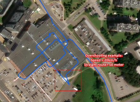
* '''Overshooting''' - May occur when the vehicle travels straight for more than 50 m at speeds below 20 km/h. In such cases, positional overshoot may be observed. An example is shown in the attached image. | |||
[[File:Dead Reckoning - Overshooting.png|300px|link=Special:Redirect/file/Dead Reckoning - Overshooting.png]] | |||
* '''Position accuracy may decrease''' - If the device cannot receive a GNSS signal for a long time, the estimated position may become less accurate. This is because the sensors inside the device can only estimate the position for a limited time without help from GNSS. | |||
For example: If a courier spends up to 30 minutes unloading in the underground car park, DR will remain accurate. Otherwise, positioning information will become less accurate. | |||
* '''Temperature effects''' - The accuracy of the position can change if the temperature is very different from when the device was last calibrated. | |||
* '''Alignment reset''' - If the device loses power or goes into sleep mode, it will need to be calibrated again. | |||
'''Tip:''' If alignment auto-save is enabled, realignment will be faster. | |||
*''' | * '''Position jumps after GNSS outages''' - Multipath occurs when reflected or diffracted GNSS signals reach the receiver, causing position errors. Since Dead Reckoning depends on GNSS for continuous correction, these multipath induced inaccuracies can lead to visible position jumps, especially in urban areas with tall buildings or obstructions. | ||
[[File:GNSS Multipath.png|350px]] | |||
=== <u>AVL ID list</u> === | |||
<table class="nd-othertables_2" style="width:100%; border-collapse: collapse;"> | |||
<tr> | <tr> | ||
< | <th style="width:8%; vertical-align: middle; text-align: left;">Property ID in AVL packet</th> | ||
< | <th style="width:15%; vertical-align: middle; text-align: center;">Property Name</th> | ||
< | <th style="width:5%; vertical-align: middle; text-align: center;">Bytes</th> | ||
<th style="width:10%; vertical-align: middle; text-align: center;">Min Value</th> | |||
<th style="width:10%; vertical-align: middle; text-align: center;">Max Value</th> | |||
<th style="width:5%; vertical-align: middle; text-align: center;">Multiplier</th> | |||
<th style="width:5%; vertical-align: middle; text-align: center;">Units</th> | |||
<th style="width:32%; vertical-align: middle; text-align: left;">Description</th> | |||
</tr> | </tr> | ||
<tr> | <tr> | ||
<td style="vertical-align: middle; text-align: center;"> | <td style="vertical-align: middle; text-align: center;">1433</td> | ||
<td style="vertical-align: middle; text-align: center;"> | <td style="vertical-align: middle; text-align: center;">Dead Reckoning alignment status</td> | ||
<td style="vertical-align: middle; text-align: center;"> | <td style="vertical-align: middle; text-align: center;">1</td> | ||
<td style="vertical-align: middle; text-align: center;">0</td> | |||
<td style="vertical-align: middle; text-align: center;">99</td> | |||
<td style="vertical-align: middle; text-align: center;">1</td> | |||
<td style="vertical-align: middle; text-align: center;"> </td> | |||
<td style="vertical-align: middle; text-align: center;">[[{{{model}}}_System#Dead_Reckoning_alignment_status|Dead Reckoning alignment status]]</td> | |||
</tr> | </tr> | ||
<tr> | <tr> | ||
<td style="vertical-align: middle; text-align: center;"> | <td style="vertical-align: middle; text-align: center;">1434</td> | ||
<td style="vertical-align: middle; text-align: center;"> | <td style="vertical-align: middle; text-align: center;">Turning alignment</td> | ||
<td style="vertical-align: middle; text-align: center;"> | <td style="vertical-align: middle; text-align: center;">1</td> | ||
<td style="vertical-align: middle; text-align: center;">0</td> | |||
<td style="vertical-align: middle; text-align: center;">100</td> | |||
<td style="vertical-align: middle; text-align: center;">1</td> | |||
<td style="vertical-align: middle; text-align: center;">%</td> | |||
<td style="vertical-align: middle; text-align: center;">[[{{{model}}}_System#Turning_alignment|Turning alignment]]</td> | |||
</tr> | </tr> | ||
<tr> | <tr> | ||
<td style="vertical-align: middle; text-align: center;"> | <td style="vertical-align: middle; text-align: center;">1435</td> | ||
<td style="vertical-align: middle; text-align: center;"> | <td style="vertical-align: middle; text-align: center;">Straight alignment</td> | ||
<td style="vertical-align: middle; text-align: center;"> | <td style="vertical-align: middle; text-align: center;">1</td> | ||
<td style="vertical-align: middle; text-align: center;">0</td> | |||
<td style="vertical-align: middle; text-align: center;">100</td> | |||
<td style="vertical-align: middle; text-align: center;">1</td> | |||
<td style="vertical-align: middle; text-align: center;">%</td> | |||
<td style="vertical-align: middle; text-align: center;">[[{{{model}}}_System#Straight alignment|Straight alignment]]</td> | |||
</tr> | </tr> | ||
</table> | |||
=== <u>Parameter list</u> === | |||
<table class="nd-othertables_2" style="width:100%; border-collapse: collapse;"> | |||
<tr> | <tr> | ||
< | <th style="width:8%; vertical-align: middle; text-align: left;">Property ID in AVL packet</th> | ||
< | <th style="width:15%; vertical-align: middle; text-align: center;">Property Name</th> | ||
< | <th style="width:5%; vertical-align: middle; text-align: center;">Bytes</th> | ||
<th style="width:10%; vertical-align: middle; text-align: center;">Min Value</th> | |||
<th style="width:10%; vertical-align: middle; text-align: center;">Max Value</th> | |||
<th style="width:5%; vertical-align: middle; text-align: center;">Multiplier</th> | |||
<th style="width:5%; vertical-align: middle; text-align: center;">Units</th> | |||
<th style="width:32%; vertical-align: middle; text-align: left;">Description</th> | |||
</tr> | </tr> | ||
<tr> | <tr> | ||
<td style="vertical-align: middle; text-align: center;"> | <td style="vertical-align: middle; text-align: center;">123</td> | ||
<td style="vertical-align: middle; text-align: center;"> | <td style="vertical-align: middle; text-align: center;">Alignment auto-save</td> | ||
<td style="vertical-align: middle; text-align: center;">-</td> | <td style="vertical-align: middle; text-align: center;">-</td> | ||
<td style="vertical-align: middle; text-align: center;">0</td> | |||
<td style="vertical-align: middle; text-align: center;">1</td> | |||
<td style="vertical-align: middle; text-align: center;">-</td> | |||
<td style="vertical-align: middle; text-align: center;">-</td> | |||
<td style="vertical-align: middle; text-align: center;">This option saves calibration data to device memory, enabling a faster recalibration after device restart. <br> '''0''' = Disable <br> '''1''' = Enable </td> | |||
</tr> | </tr> | ||
<tr> | <tr> | ||
<td style="vertical-align: middle; text-align: center;"> | <td style="vertical-align: middle; text-align: center;">124</td> | ||
<td style="vertical-align: middle; text-align: center;"> | <td style="vertical-align: middle; text-align: center;">Standby timeout</td> | ||
<td style="vertical-align: middle; text-align: center;">-</td> | <td style="vertical-align: middle; text-align: center;">-</td> | ||
<td style="vertical-align: middle; text-align: center;">1</td> | |||
<td style="vertical-align: middle; text-align: center;">65535</td> | |||
<td style="vertical-align: middle; text-align: center;">1</td> | |||
<td style="vertical-align: middle; text-align: center;">(s) seconds</td> | |||
<td style="vertical-align: middle; text-align: center;">The standby timeout is the time after which device will attempt to correct the position based on correction strategy.<br> Default value = '''1800''' </td> | |||
</tr> | </tr> | ||
<tr> | <tr> | ||
<td style="vertical-align: middle; text-align: center;"> | <td style="vertical-align: middle; text-align: center;">125</td> | ||
<td style="vertical-align: middle; text-align: center;"> | <td style="vertical-align: middle; text-align: center;">Standby mode</td> | ||
<td style="vertical-align: middle; text-align: center;"> | <td style="vertical-align: middle; text-align: center;">-</td> | ||
</ | <td style="vertical-align: middle; text-align: center;">0</td> | ||
<td style="vertical-align: middle; text-align: center;">1</td> | |||
< | <td style="vertical-align: middle; text-align: center;">-</td> | ||
<td style="vertical-align: middle; text-align: center;"> | <td style="vertical-align: middle; text-align: center;">-</td> | ||
<td style="vertical-align: middle; text-align: center;"> | <td style="vertical-align: middle; text-align: center;">The standby mode is the mode in which the device will attempt to correct the position based on correction strategy. <br>'''0''' = Realignment<br>'''1''' = Preserve alignment</td> | ||
<td style="vertical-align: middle; text-align: center;"> | |||
</tr> | </tr> | ||
</table> | |||
Latest revision as of 13:20, 30 April 2026
Dead Reckoning
Dead Reckoning is a navigation technique used to estimate current position of vehicle , direction of movement, based on its previous position and known speed. It uses additional sensor data to correct the position received from GNSS receiver.
Usage of Dead Reckoning is essential in scenarios where GNSS signal is weak or unavailable, such as underground parking lots, tunnels or dense forests.
Key points to understand before utilizing the Dead Reckoning functionality:
- Installation
- Configuration
- Alignment
Prerequisites and Important Settings
- Device mounting quality – Correct device mounting is critical for Dead Reckoning operation. Improper mounting may result in incorrect sensor data and unreliable Dead Reckoning performance.
- Dead Reckoning alignment maintenance – If Dead Reckoning alignment parameters are no longer valid, send the DR_RESET command and perform calibration.
- Electric and hybrid vehicles – For electric and hybrid vehicles, DIN1 should be used for movement detection to ensure correct Dead Reckoning operation.
- Dead Reckoning is not supported for two‑wheeled vehicles (e.g., motorcycles, scooters).
Basic Operation
Installation
The device must be mounted firmly in the vehicle, with good visibility of the sky. Failure to ensure proper mounting will result in inability to calibrate the device or inaccurate position estimation. Following examples ensure that the GNSS antenna is facing towards the sky and there are no physical obstacles, like metal plates, wires, are blocking the GNSS signal.
Good mounting examples ( If vehicle has a heated windshield, you should look for an alternative mounting location in the trunk, on some sturdy metal closer to backseat window):

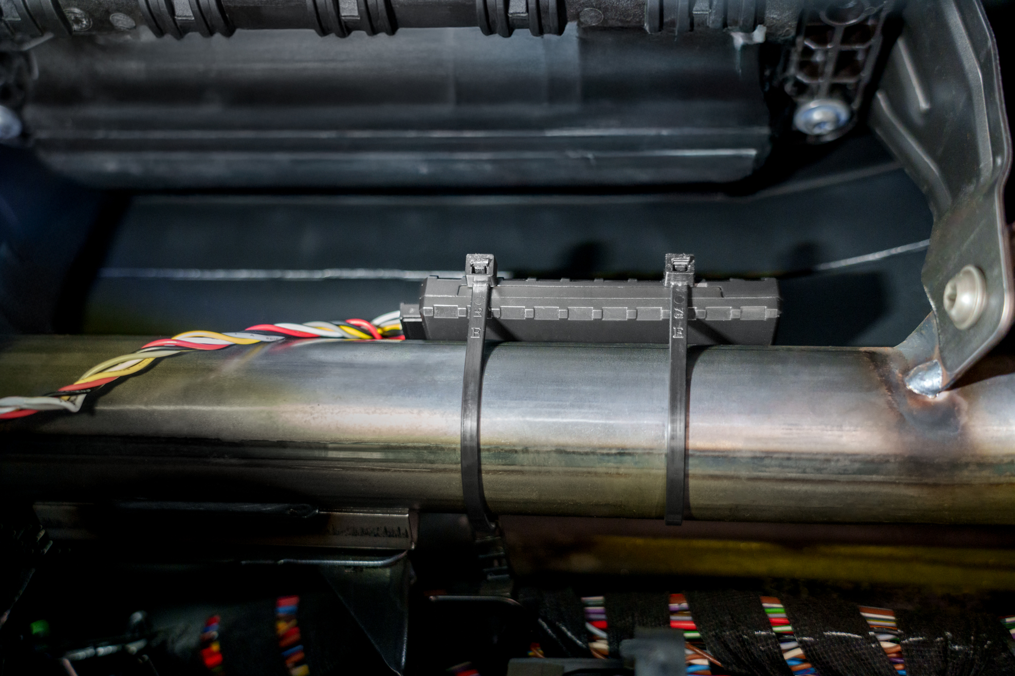
Bad mounting examples:


Configuration

The Dead Reckoning feature is configurable via the Dead Reckoning section in the GNSS settings group under System view in TCT.
Parameter list can be found [[{{{model}}}_System#Parameter_list|here]].
Dead Reckoning alignment status
The Dead Reckoning alignment status is a 1-byte AVL ID (1433) that indicates the current status of the Dead Reckoning alignment. The possible values are:
- 0 - Unknown: Dead Reckoning status is unknown.
- 1 - Init: Dead Reckoning alignment is initializing.
- 2 - Coarse: Dead Reckoning is in alignment stage.
- 3 - Stable: Dead Reckoning alignment stage has been completed. Estimation stage is in progress.
- 99 - Standby: Dead Reckoning is in standby mode (NOTE: this status is availabe with 3.7.X or newer firmware version)
Turning alignment
The turning alignment is a 1-byte AVL ID (1434) that indicates the current percentage of the turning alignment of the device.
Straight alignment
The straight alignment is a 1-byte AVL ID (1435) that indicates the current percentage of the straight alignment of the device.
Alignment
Once device mounting adheres to the guidelines, alignment can be performed. The device must finish a specific alignment process to determine its mounting orientation. During this process, there are specific conditions that must be met:
- The device must be stationary with clear sky visibility for at least 3 minutes.
- Vehicle speed during alignment should be between 10 km/h and 100 km/h, with varying speeds preferred over extended constant-speed driving.
- Avoid driving in underground tunnels or areas with poor GNSS signal, otherwise alignment needs to be restarted from the second step.

Standby mode
Standby Mode preserves Dead Reckoning calibration indefinitely, ensuring accurate position estimation after extended GNSS outages (e.g., a week in underground parking), and supports unlimited duration in this mode while maintaining full calibration integrity.
Standby Mode has two behavior options:
- Realignment – Calibration alignment is discarded after the Standby Timeout period.
- Preserve alignment – Calibration alignment is retained during prolonged stationary periods.
Prerequisites and important Settings
- If the device is remounted, send the DR_Reset SMS command and perform a full recalibration. This ensures all orientation- and sensor alignment parameters are refreshed, preventing inaccurate Dead Reckoning calculations after the installation change.
Basic Operation
Entering Standby Mode
The device can enter Standby Mode in two scenarios:
- No movement detected
If the device detects absence of movement, Dead Reckoning enters Standby Mode after the timeout defined by Standby timeout (ID 124) elapses.
- Device enters sleep mode
When the device transitions into sleep mode, the GNSS receiver is switched to power saving mode.
Before GNSS powers down, Dead Reckoning enters Standby Mode immediately, the scenario is paused, and the device proceeds into sleep mode.
Exiting Standby Mode
Standby Mode can be exited in the following cases:
- Movement is detected
When movement is detected, the device exits Standby Mode and resumes normal Dead Reckoning operation. If no movement is detected, Dead Reckoning remains in Standby Mode.
Key Performance Indicators (based on performed tests)
- GNSS denied operation (1 km)
- When driving 1 km without a GNSS signal (including 15–20 turns), the positional error is ≤ 25 m, achieved in at least 8 out of 10 field tests.
- Dead Reckoning continues operating beyond 1 km; however, positional error may increase after this threshold.
- When driving 1 km without a GNSS signal (including 15–20 turns), the positional error is ≤ 25 m, achieved in at least 8 out of 10 field tests.
- Recovery after DR Standby (Sleep Mode)
- After exiting DR Standby (Sleep Mode), the system correctly reconstructs the driven route for up to 5 minutes or 1000 m, with a positional error of ≤ 50 m, achieved in at least 8 out of 10 field tests.
- After exiting DR Standby (Sleep Mode), the system correctly reconstructs the driven route for up to 5 minutes or 1000 m, with a positional error of ≤ 50 m, achieved in at least 8 out of 10 field tests.
- Real world driving variability
- Real world driving conditions may vary and can impact performance results.
Limitations, Edge Cases & Additional Notes
There are some important things to keep in mind when using the Dead Reckoning functionality. The algorithm tries to correct for these issues, but sometimes they can still affect how well Dead Reckoning works.
- Loss of alignment during drifting – Dead Reckoning alignment will be lost during drifting, when the actual movement vector does not correspond to the vehicle heading. Re‑alignment is required.
- Overshooting - May occur when the vehicle travels straight for more than 50 m at speeds below 20 km/h. In such cases, positional overshoot may be observed. An example is shown in the attached image.
- Position accuracy may decrease - If the device cannot receive a GNSS signal for a long time, the estimated position may become less accurate. This is because the sensors inside the device can only estimate the position for a limited time without help from GNSS.
For example: If a courier spends up to 30 minutes unloading in the underground car park, DR will remain accurate. Otherwise, positioning information will become less accurate.
- Temperature effects - The accuracy of the position can change if the temperature is very different from when the device was last calibrated.
- Alignment reset - If the device loses power or goes into sleep mode, it will need to be calibrated again.
Tip: If alignment auto-save is enabled, realignment will be faster.
- Position jumps after GNSS outages - Multipath occurs when reflected or diffracted GNSS signals reach the receiver, causing position errors. Since Dead Reckoning depends on GNSS for continuous correction, these multipath induced inaccuracies can lead to visible position jumps, especially in urban areas with tall buildings or obstructions.

AVL ID list
| Property ID in AVL packet | Property Name | Bytes | Min Value | Max Value | Multiplier | Units | Description |
|---|---|---|---|---|---|---|---|
| 1433 | Dead Reckoning alignment status | 1 | 0 | 99 | 1 | [[{{{model}}}_System#Dead_Reckoning_alignment_status|Dead Reckoning alignment status]] | |
| 1434 | Turning alignment | 1 | 0 | 100 | 1 | % | [[{{{model}}}_System#Turning_alignment|Turning alignment]] |
| 1435 | Straight alignment | 1 | 0 | 100 | 1 | % | [[{{{model}}}_System#Straight alignment|Straight alignment]] |
Parameter list
| Property ID in AVL packet | Property Name | Bytes | Min Value | Max Value | Multiplier | Units | Description |
|---|---|---|---|---|---|---|---|
| 123 | Alignment auto-save | - | 0 | 1 | - | - | This option saves calibration data to device memory, enabling a faster recalibration after device restart. 0 = Disable 1 = Enable |
| 124 | Standby timeout | - | 1 | 65535 | 1 | (s) seconds | The standby timeout is the time after which device will attempt to correct the position based on correction strategy. Default value = 1800 |
| 125 | Standby mode | - | 0 | 1 | - | - | The standby mode is the mode in which the device will attempt to correct the position based on correction strategy. 0 = Realignment 1 = Preserve alignment |