Difference between revisions of "Template:FMB2 Possible mounting zones"
From Wiki Knowledge Base | Teltonika GPS
Simkunas.ma (talk | contribs) |
Simkunas.ma (talk | contribs) |
||
| (38 intermediate revisions by the same user not shown) | |||
| Line 1: | Line 1: | ||
| − | + | <font size="+3"><span style=color:#104996>'''Mounting recommendations'''</span></font> | |
| + | <span style=color:#F49E21></span> | ||
| + | ==<font size="+2">Trucks</font>== | ||
<font size="+1"> | <font size="+1"> | ||
| − | It is strongly recommended to mount FMB2YX outside of the vehicle with the sticker direction to the sky [[Image:Trucks.png|800px|right]] | + | * It is strongly recommended to mount FMB2YX outside of the vehicle with the sticker direction to the sky [[Image:Trucks.png|800px|right]] |
</font> | </font> | ||
| − | < | + | <font size="+2"><span style=color:#F49E21> 2. </span> Connecting power source. </font> |
| − | + | <font size="+1"> | |
| − | + | * Be sure that after the car computer goes to sleep mode, power might be still available on the power wires. Depending on the car model, this may happen in 5 to 30 minutes period. | |
| − | <font size="+1"> | + | * When the module is connected, measure the voltage again to make sure it did not decrease. |
| − | + | * It is recommended to connect to the main power cable in the fuse box. | |
| − | + | * 3 A, 125 V external fuse shall be used. | |
| − | + | </font> | |
| − | + | <font size="+2"><span style=color:#F49E21> 3. </span> Connecting ignition wire. </font> | |
| − | + | <font size="+1"> | |
| − | < | + | * Be sure to check if it is a real ignition wire i. e. power does not disappear after starting the engine. |
| − | + | * Check if this is not an ACC wire (when key is in the first position, most of the vehicle electronics are available). | |
| − | + | * Check if power is still available when you turn off any of vehicles devices. | |
| − | + | * Ignition is connected to the ignition relay output. As alternative, any other relay, which has power output when ignition is on, may be chosen. | |
| + | </font> | ||
| + | <font size="+2"><span style=color:#F49E21> 4. </span> Connecting ground wire. </font> | ||
<font size="+1"> | <font size="+1"> | ||
| − | + | * Ground wire is connected to the vehicle frame or metal parts that are fixed to the frame. | |
| + | * If the wire is fixed with the bolt, the loop must be connected to the end of the wire. | ||
| + | * For better contact scrub paint from the spot where loop is going to be connected. | ||
</font> | </font> | ||
Revision as of 14:17, 29 May 2018
Mounting recommendations
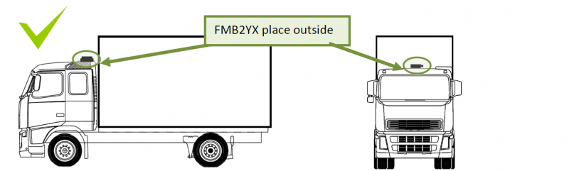
Trucks
- It is strongly recommended to mount FMB2YX outside of the vehicle with the sticker direction to the sky

2. Connecting power source.
- Be sure that after the car computer goes to sleep mode, power might be still available on the power wires. Depending on the car model, this may happen in 5 to 30 minutes period.
- When the module is connected, measure the voltage again to make sure it did not decrease.
- It is recommended to connect to the main power cable in the fuse box.
- 3 A, 125 V external fuse shall be used.
3. Connecting ignition wire.
- Be sure to check if it is a real ignition wire i. e. power does not disappear after starting the engine.
- Check if this is not an ACC wire (when key is in the first position, most of the vehicle electronics are available).
- Check if power is still available when you turn off any of vehicles devices.
- Ignition is connected to the ignition relay output. As alternative, any other relay, which has power output when ignition is on, may be chosen.
4. Connecting ground wire.
- Ground wire is connected to the vehicle frame or metal parts that are fixed to the frame.
- If the wire is fixed with the bolt, the loop must be connected to the end of the wire.
- For better contact scrub paint from the spot where loop is going to be connected.

