Difference between revisions of "Template:FMB964 Accessories"
From Wiki Knowledge Base | Teltonika GPS
| Line 27: | Line 27: | ||
! style="text-align: left; vertical-align: top;" | Immobilizer relay | ! style="text-align: left; vertical-align: top;" | Immobilizer relay | ||
! style="text-align: left; vertical-align: top;" | Immobilizer relay connection to {{{model|FMB9YX}}} output | ! style="text-align: left; vertical-align: top;" | Immobilizer relay connection to {{{model|FMB9YX}}} output | ||
| − | |||
| − | |||
| − | |||
| − | |||
| − | |||
| − | |||
| − | |||
| − | |||
| − | |||
| − | |||
|- | |- | ||
Revision as of 09:10, 19 July 2018
| Please order accessories separately as they are not included into device package. |
| Accessory and its description | Accessory connection schematic |
|---|---|
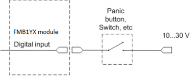
| Alarm buttons, door sensors etc. | Panic button connection to FMB9YX |
| Alarm buttons, door sensors, ignition, etc. have two output states: high or low. FMB9YX Digital inputs are used to detect these states. | |
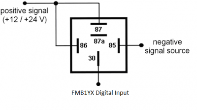
| Relays | Inverting relay connection to FMB9YX |
| In cases when sensor output signal is negative, an additional relay has to be installed to convert negative signal to positive. | |
| Immobilizer relay | Immobilizer relay connection to FMB9YX output |

