Difference between revisions of "Template:FMT1 First start card"
From Wiki Knowledge Base | Teltonika GPS
m (Protected "Template:FMT1 First start card" ([Edit=Allow only administrators] (indefinite) [Move=Allow only administrators] (indefinite))) |
|||
| (12 intermediate revisions by 4 users not shown) | |||
| Line 2: | Line 2: | ||
| − | <b>{{{description|Special and small waterproof GNSS tracker with built-in accelerometer | + | <b>{{{description|Special and small waterproof GNSS tracker with built-in accelerometer and gyroscope}}}</b>{{{pic|[[Image:FMT100-1-demo.png|400px|right]]}}} |
| Line 14: | Line 14: | ||
[[Image:FMT100_know_your_device-2.png|center|1000px]] | [[Image:FMT100_know_your_device-2.png|center|1000px]] | ||
| − | |||
| − | |||
| − | {| class="wikitable" | + | ===Pinout=== |
| + | |||
| + | {| class="wikitable" style="width:50%;" | ||
|+ | |+ | ||
| − | ! style="width: | + | ! style="width:10%; border: 1px solid white; border-bottom: 2px solid #0054A6; background: white; color: #0054A6; text-align: left;"| PIN NUMBER |
| − | ! style="width: | + | ! style="width:15%; border: 1px solid white; border-bottom: 2px solid #0054A6; background: white; color: #0054A6; text-align: left;"| PIN NAME |
| − | ! style="width:25%; border: 1px solid white; border-bottom: 2px solid #0054A6; background: white; color: #0054A6; text-align: left;" |DESCRIPTION | + | ! style="width:25%; border: 1px solid white; border-bottom: 2px solid #0054A6; background: white; color: #0054A6; text-align: left;"| DESCRIPTION |
| − | |||
|- | |- | ||
| style="border: 1px solid white; border-bottom: 2px solid #E8E8E8; text-align: left; vertical-align: center; background: white;" | 1 | | style="border: 1px solid white; border-bottom: 2px solid #E8E8E8; text-align: left; vertical-align: center; background: white;" | 1 | ||
| Line 28: | Line 27: | ||
| style="border: 1px solid white; border-bottom: 2px solid #E8E8E8; text-align: left; vertical-align: center; background: white;" | '''<span style="color:red;">(Red)</span>''' Power supply (+10-30 V DC) | | style="border: 1px solid white; border-bottom: 2px solid #E8E8E8; text-align: left; vertical-align: center; background: white;" | '''<span style="color:red;">(Red)</span>''' Power supply (+10-30 V DC) | ||
|- | |- | ||
| − | |||
| − | |||
| − | |||
| − | |||
| − | |||
=='''Set up your device'''== | =='''Set up your device'''== | ||
| Line 39: | Line 33: | ||
# Unscrew '''6 screws''' counterclockwise. | # Unscrew '''6 screws''' counterclockwise. | ||
# Remove the '''cover'''. | # Remove the '''cover'''. | ||
| − | # Insert '''Micro-SIM''' card as shown with '''PIN request disabled''' or read {{{sim_pin|[[FMT100 Security info| | + | # Insert '''Micro-SIM''' card as shown with '''PIN request disabled''' or read {{{sim_pin|[[FMT100 Security info|Security info]]}}} how to enter it later with [[Teltonika Configurator]]. Make sure that Micro-SIM card '''cut-off corner''' is pointing forward to slot. |
# Connect the '''battery''' as shown to device. Position the battery in place where it does not obstruct other components. | # Connect the '''battery''' as shown to device. Position the battery in place where it does not obstruct other components. | ||
# After '''configuration''', see [[FMT100_First_Start#PC Connection (Windows)|PC Connection (Windows)]], attach device '''cover''' back and '''screw''' in all screws. | # After '''configuration''', see [[FMT100_First_Start#PC Connection (Windows)|PC Connection (Windows)]], attach device '''cover''' back and '''screw''' in all screws. | ||
Revision as of 10:35, 20 December 2018
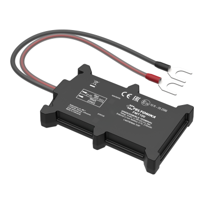
Special and small waterproof GNSS tracker with built-in accelerometer and gyroscope
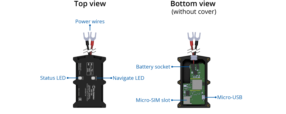
Know your device
Pinout
Set up your device
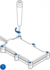
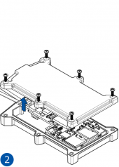
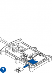
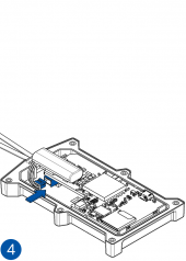
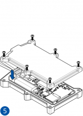
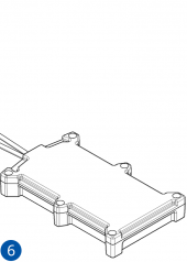
How to insert Micro-SIM card and connect the battery
- Unscrew 6 screws counterclockwise.
- Remove the cover.
- Insert Micro-SIM card as shown with PIN request disabled or read Security info how to enter it later with Teltonika Configurator. Make sure that Micro-SIM card cut-off corner is pointing forward to slot.
- Connect the battery as shown to device. Position the battery in place where it does not obstruct other components.
- After configuration, see PC Connection (Windows), attach device cover back and screw in all screws.
- Device is ready to be mounted.
| PIN NUMBER | PIN NAME | DESCRIPTION |
|---|---|---|
| 1 | VCC (10-30)V DC (+) | (Red) Power supply (+10-30 V DC) |
| Micro-SIM card insertion/removal must be performed when device is powered off – external voltage and battery are disconnected. Otherwise Micro-SIM card might be damaged or device will not detect it. |

