FMB630 Features: Difference between revisions
Created page with "Category:FMB630 Advanced Configuration" |
m Protected "FMB630 Features" ([Edit=Allow only administrators] (indefinite) [Move=Allow only administrators] (indefinite)) |
||
| (2 intermediate revisions by 2 users not shown) | |||
| Line 1: | Line 1: | ||
[[Category:FMB630 | __TOC__ | ||
=sMode= | |||
{{Template:FMB630_sMode|model=FMB630|image=[[Image:FMB630_sMode.png|500px]]}} | |||
=Scenarios= | |||
{{Template:FMB630_Scenarios|image=[[Image:FMB630_scenarios.png|700px]]}} | |||
=Trip= | |||
{{Template:FMB630_Trip|model=FMB630|image=[[Image:FMB630_trip.png|700px]]}} | |||
=Geofencing= | |||
{{Template:FMB630_Geofencing|model=FMB630|geofencing1=[[Image:FMB630_geofencing1.png|750px]]|geofencing2=[[Image:FMB630_geofencing2.png|300px]]}} | |||
=Auto Geofence= | |||
{{Template:FMB630_Auto_Geofence|image=[[Image:FMB630_autogeofencing.png|600px]]}} | |||
=Towing detection= | |||
{{Template:FMB630_Towing_detection|model=FMB630|image=[[Image:FMB630_towing_detection.png|700px]]}} | |||
=iButton List= | |||
{{Template:FMB630_iButton_List|image=[[Image:FMB630_ibutton_list.png|600px]]}} | |||
[[Category:FMB630 Configuration]] | |||
Latest revision as of 09:08, 5 November 2019
Main Page > EOL Products > FMB630 > FMB630 Configuration > FMB630 FeaturessMode
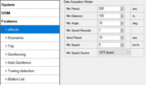
FMB630 is able to collect records using four methods at the same time: time, distance, speed and angle based data acquisition. Send and Save Parameters configuration is available in Features->sMode category:
- Min Period – time period change that initializes record save.
- Min Angle – angle change that initializes record save (only if vehicle is moving).
- Min Distance – distance change that initializes record save (only if vehicle is moving).
- Send period – GPRS data sending to server period. Module makes attempts to send collected data to server every defined period. If it does not have enough records (depends on parameter Min. Saved Records described above), it tries again after defined time interval.
- Min speed – Speed based data acquiring. Records are being acquired when speed difference between last recorded coordinate and current position is greater than the defined value. Entering zero disables data acquisition depending on speed. This method is suitable for urban territories. Min speed source can be selected by GPS speed, LVCAN speed, ALLCAN speed, FMS Speed or KLINE speed.
Scenarios
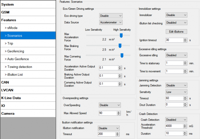
In scenarios window seven different scenarios are available (Eco/Green Driving, Immobilizer/ Authorizing driving, iButton notification, Excessive Idling, Jamming detection, over speeding and Crash detection). They have six possible states: disabled, no DOUT control, DOUT1 control, DOUT2 control, DOUT3 control, DOUT4 control (expect excessive idling and Crash detection). Excessive idling and Crash detection scenario has two states: Disable and Enable. All scenarios can be activated at the same time and all scenarios that use DOUT can control the same DOUT.
Crash Detection
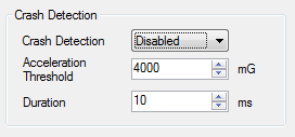
If Crash Detection is enabled, it monitors acceleration on each axis which helps to detect an accident. Threshold and Duration values are set depending on the impact magnitude that is required to be detected. FM63XY can detect events ranging between a slight tapping on the device and a severe accident.
Crash Detection has AVL_ID of 247 with values of 0 - Crash Not detected and 1 - Crash Detected.
If Crash Detection is enabled, AVL_ID of 247 will be saved to periodical record as LOW priority event.
Trip
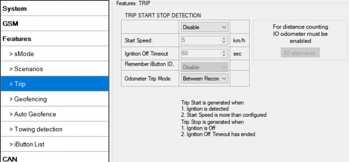
Trip window offers user to configure Trip feature. If Trip is enabled configuration of parameters is available:
- Start Speed – speed, which is detected as minimum speed to indicate Trip start.
- Ignition Off Timeout – timeout to wait if ignition was off, to detect Trip stop.
- Remember iButton ID- Send ibutton value to server while trip is detected
- Odometer Trip Mode – Between records or Continuous can be chosen. For this feature I/O Trip Odometer value feature must be enabled.
FMB630 Features->Trip Configuration window
If I/O Trip Odometer is enabled and Odometer Trip Mode distance counting variable is set to Continuous, Trip distance is going to be counted continuously (from Trip start to Trip stop). This value is written to I/O Odometer value field. When Trip is over and next Trip begins, Odometer Trip value is reset to zero, and it is counted continuously again.
If I/O Trip Odometer is enabled and Continuous Distance Counting variable is set to “Between Records”, then distance is going to be counted only between every record made. This value is written to I/O Trip Odometer value field and reset to zero every new record until Trip stops. If later all Odometer values are summed up manually user gets distance driven over the whole Trip period.
When trip is enabled and Remember iButton ID in trip settings is also enabled, device will remember iButton (during trip) when it is attached. Ibutton value will lose after reset. When iButton value is saved, it will be stored in iButton I/O and will be added with every record. When new iButton is attached, its ID will be added to iButton I/O and old iButton value will be forgotten. When iButton is attached and ignition is not ON, then iButton is saved but value will not be added to I/O. If iButton is not attached in Ignition OFF timeout, then iButton value is removed. It is added only when ignition is set on and trip event occurred. The iButton is removed from iButton IO (set to 0) when trip end event occurs.
Geofencing
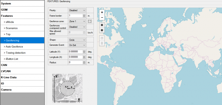
FMB630 has 20 configurable Geofence zones and it can generate event when defined Geofence zone border has been crossed. Or overspeeding is occured in a configured geofence zone.
- Frame border – frame border is an additional border around Geofence zone. It is additional area around defined zone used to prevent false event recording when object stops on the border of the area and because of GPS errors some records are made inside area and some – outside. Event is generated only when both borders are crossed. See Figure 39 for details: track 1 is considered to enter the area while track 2 does not.
- Geofence zone - User can configure upto 50 geofence zones without interfering DOUT control or allowed speed limit of other zones.
- Geofence overspeed control – Option to use any DOUT if overspeed event happens in a configured geozone.
- Max allowed speed – Max allowed speed in a configured geozone
- Shape – can be rectangular or circle
- Priority – priority of Geofence event: low, high or panic, SW21, SW22, SW23, SW24. These levels define priority of event information sending to server. See I/O element description for more details about priorities.
- Generate event (On entrance, On exit, On both) – choose when record will be generated (or no event);
- X1 – geofence zone left bottom corner X coordinate;
- Y1 – geofence zone left bottom corner Y coordinate;
- X2 or R – geofence zone upper right corner X coordinate (radius of circle when Circular zone used);
- Y2 – geofence zone upper right corner Y coordinate;
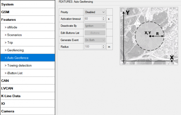
Auto Geofence
AutoGeofence – the last known position after movement = off. If your car is being taken away – you can be notified. The shape and size of the geofence zones are configurable. There is a possibility to state whether entering in or out of the geofence triggers an asynchronous message.
Auto Geofencing option can be configured by following parameters:
- Activation TMO – Time period before Geofence is activated after vehicle stops.
- Deactivate By:
- Ignition – if ignition becomes high it will drop AutoGeofenze Zone
- iButton – if iButton is attached it will drop AutoGeofence Zone
- Edit iButton List – if list is not empty, attached iButton is tested against iButton list, if match is found AutoGeofence zone is dropped.
- Priority – Priority of generated event, which will be applied to saved record.
- Generate Event:
- Enter Event – Event generation on Geofence entrance.
- Exit Event – Event generation on Geofence exit.
- On Both - Event generation on Geofence entrance or exit.
- No Event
Auto Geofencing does not require entering coordinates, instead it requires GPS visibility. If vehicle stopped and activation timeout is reached, Auto Geofence will be created around the vehicles last position by set Radius value. Auto Geofence event generation works the same as Geofencing mentioned above.
Towing detection
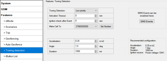
FMB630 activates towing function when below conditions are met:
- Ignition (configured Ignition Source) is OFF.
- Activation Timeout (set in Towing detection features) is reached.
When Activation Timeout is reached and Ignition is OFF, FMB630 monitors accelerometer data. If Acceleration or Angle value reaches configured threshold for configured time (in ms), device again checks Ignition state. If Ignition is still OFF according to configured "Ignition check after Event" time, then event is generated and can send sms or make call if configured. Function will be reactivated after FMB630 again detects change of Ignition state from ON to OFF.
- Activation timeout – Activation timeout is time after which FMB630 turns ON towing detection function if other condition mets (Ignition OFF state detected). It is measured in minutes.
- Make Call to – if function enabled makes call to specified phone number (configured in predefined numbers)
- Acceleration and Angle – values used to detect towing when ignition is OFF.
- Duration – defines time period to check Acceleration and Angle values.
iButton List
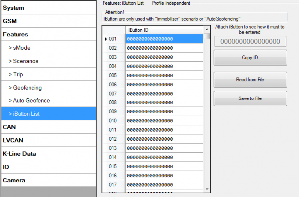
IButton list is used to enter authorized iButton ID codes, which are used to authenticate driver in Immobilizer scenario or Auto Geofencing options.
iButton value must be entered as it is written on it. User can save 500 iButtons to .csv file and read them from same file using Read from File and save to file buttons. User can also enter ibutton key ID in Ibutton ID list by attaching ibutton key to reader then connecting reader to device after that click ‘copy ID’ and paste ibutton key in ibutton ID list.

