Difference between revisions of "Template:FMU1 First start card"
From Wiki Knowledge Base | Teltonika GPS
| (2 intermediate revisions by 2 users not shown) | |||
| Line 1: | Line 1: | ||
[[Image:Qsg_rut950_teltonika.PNG|centre]] | [[Image:Qsg_rut950_teltonika.PNG|centre]] | ||
| − | {{{pic|[[Image: | + | |
| − | + | ||
| + | |||
| + | <b>{{{description|GNSS/GSM/Bluetooth tracker with internal GNSS/GSM antennas}}}</b>{{{pic|[[Image:Fmu125 man.png|400px|right]]}}} | ||
| + | |||
| Line 10: | Line 13: | ||
#Gently remove {{{model|FMU1YX}}} '''cover''' using '''plastic pry tool''' from both sides. | #Gently remove {{{model|FMU1YX}}} '''cover''' using '''plastic pry tool''' from both sides. | ||
| − | #Insert '''{{{sim_type|Micro-}}}SIM''' card as shown with '''PIN request disabled''' or read {{{sim_pin|[[ | + | #Insert '''{{{sim_type|Micro-}}}SIM''' card as shown with '''PIN request disabled''' or read {{{sim_pin|[[FMU120 Security info|'''Security info''']]}}} how to enter it later in Configurator. Make sure that {{{sim_type|Micro-}}}SIM card '''cut-off corner''' is pointing forward to slot. {{{dual_sim|'''SIM slot 1''' is closer to PCB, '''SIM slot 2''' is the upper one.}}} |
#Attach device '''cover''' back. | #Attach device '''cover''' back. | ||
#Device is ready to be connected. | #Device is ready to be connected. | ||
[[Image:{{{sim_insert_pic1|FMB1_cover1_correct.png}}}|260px]][[Image:{{{sim_insert_pic2|FMB1_cover2_correct.png}}}|260px]][[Image:{{{sim_insert_pic3|FMB1_cover3_correct.png}}}|260px]][[Image:{{{sim_insert_pic4|FMB1_cover4_correct.png}}}|260px]] | [[Image:{{{sim_insert_pic1|FMB1_cover1_correct.png}}}|260px]][[Image:{{{sim_insert_pic2|FMB1_cover2_correct.png}}}|260px]][[Image:{{{sim_insert_pic3|FMB1_cover3_correct.png}}}|260px]][[Image:{{{sim_insert_pic4|FMB1_cover4_correct.png}}}|260px]] | ||
| − | |||
{| | {| | ||
| − | + | ![[File:Alert.png|left]] | |
| − | + | !'''Micro-SIM card insertion/removal must be performed when device is powered off – external voltage and internal battery disconnected. Otherwise Micro-SIM card might be damaged or device will not detect it.''' | |
|} | |} | ||
Revision as of 13:42, 25 June 2020
GNSS/GSM/Bluetooth tracker with internal GNSS/GSM antennas
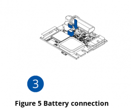
How to insert Micro-SIM card and connect the battery
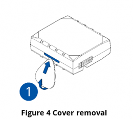
- Gently remove FMU1YX cover using plastic pry tool from both sides.
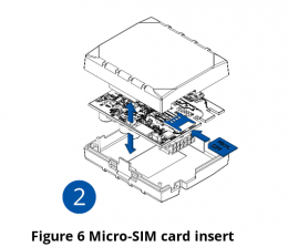
- Insert Micro-SIM card as shown with PIN request disabled or read Security info how to enter it later in Configurator. Make sure that Micro-SIM card cut-off corner is pointing forward to slot. SIM slot 1 is closer to PCB, SIM slot 2 is the upper one.
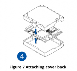
- Attach device cover back.
- Device is ready to be connected.
| Micro-SIM card insertion/removal must be performed when device is powered off – external voltage and internal battery disconnected. Otherwise Micro-SIM card might be damaged or device will not detect it. |
|---|


