Template:FMB640 Accessories: Difference between revisions
Appearance
mNo edit summary |
No edit summary |
||
| (9 intermediate revisions by 3 users not shown) | |||
| Line 1: | Line 1: | ||
{| class=" | {| class="nd-othertables_2" style="border-style: solid; border-width: 0px" | ||
|+ | |+ | ||
|- | |- | ||
| style="text-align: left | | style="text-align: left;" | [[Image:Bw_nb.png|50px]] | ||
| style="text-align: left | | style="text-align: left;" | Please order accessories separately as they are not included into device package. | ||
|- | |- | ||
|} | |} | ||
{| class=" | {| class="nd-othertables_2" | ||
|+ | |+ | ||
! style="width: 300px | ! style="width: 300px; color: white;" | Accessory and its description | ||
! style="width: 500px | ! style="width: 500px; color: white;" | Accessory connection schematic | ||
|- | |- | ||
| Line 18: | Line 18: | ||
|- | |- | ||
| style="text-align: left; vertical-align: top;" | A fuel tank level sensor which indicates the approximate fuel level on the driver's indicator panel exists in most cars. If the sensor returns analogue signal proportional to fuel level it can be connected to {{{model|FMB640}}} Analog input. After connection to the tank fuel level sensor a calibration is needed because most fuel tank sensors are not linear. Calibration is performed by measuring voltage values resulting from the volume of fuel in tank. | | style="text-align: left; vertical-align: top;" | A fuel tank level sensor which indicates the approximate fuel level on the driver's indicator panel exists in most cars. If the sensor returns analogue signal proportional to fuel level it can be connected to {{{model|FMB640}}} Analog input. After connection to the tank fuel level sensor a calibration is needed because most fuel tank sensors are not linear. Calibration is performed by measuring voltage values resulting from the volume of fuel in tank. | ||
| style="text-align: left; vertical-align: top;" | [[Image:FMB640_Fuel_Sensor.png|250px|center]] | | style="text-align: left; vertical-align: top;" | [[Image:{{{fuel_sensor|FMB640_Fuel_Sensor.png}}}|250px|center]] | ||
|- | |- | ||
! style="text-align: left; vertical-align: top;" | Alarm buttons, door sensors etc. | ! style="text-align: left; vertical-align: top;" | Alarm buttons, door sensors etc. | ||
| Line 24: | Line 24: | ||
|- | |- | ||
| style="text-align: left; vertical-align: top;" | Alarm buttons, door sensors, ignition, etc. have two output states: high or low. {{{model|FMB640}}} Digital inputs are used to detect these states. | | style="text-align: left; vertical-align: top;" | Alarm buttons, door sensors, ignition, etc. have two output states: high or low. {{{model|FMB640}}} Digital inputs are used to detect these states. | ||
| style="text-align: left; vertical-align: top;" | [[Image:FMB640_Panic_button.png|400px|center]] | | style="text-align: left; vertical-align: top;" | [[Image:{{{panic_button|FMB640_Panic_button.png}}}|400px|center]] | ||
|- | |- | ||
! style="text-align: left; vertical-align: top;" | Relays | ! style="text-align: left; vertical-align: top;" | Relays | ||
| Line 30: | Line 30: | ||
|- | |- | ||
| style="text-align: left; vertical-align: top;" | In cases when sensor output signal is negative, an additional relay has to be installed to convert negative signal to positive. | | style="text-align: left; vertical-align: top;" | In cases when sensor output signal is negative, an additional relay has to be installed to convert negative signal to positive. | ||
| style="text-align: left; vertical-align: top;" | [[Image:FMB640_inv_relay.png|400px|center]] | | style="text-align: left; vertical-align: top;" | [[Image:{{{inv_relay|FMB640_inv_relay.png}}}|400px|center]] | ||
|- | |- | ||
! style="text-align: left; vertical-align: top;" | Immobilizer relay | ! style="text-align: left; vertical-align: top;" | Immobilizer relay | ||
| Line 36: | Line 36: | ||
|- | |- | ||
| style="text-align: left; vertical-align: top;" | When connected as shown on the right hand side, {{{model|FMB640}}} disables engine starter when output is ON. | | style="text-align: left; vertical-align: top;" | When connected as shown on the right hand side, {{{model|FMB640}}} disables engine starter when output is ON. | ||
| style="text-align: left; vertical-align: top;" | [[Image:Sch_fmb1yx_imb_relay.png|400px|center]] | | style="text-align: left; vertical-align: top;" | [[Image:{{{imb_relay|Sch_fmb1yx_imb_relay.png}}}|400px|center]] | ||
|- | |- | ||
! style="text-align: left; vertical-align: top;" | Automotive relay | ! style="text-align: left; vertical-align: top;" | Automotive relay | ||
| Line 42: | Line 42: | ||
|- | |- | ||
|- | |- | ||
| style="text-align: left; vertical-align: top;" | An ordinary automotive relay is used to invert input signal or to immobilize engine starter. Note that relays can be 12 V or 24 V capable.<br/>[[Image:Pic_relay.png|150px|center]] | | style="text-align: left; vertical-align: top;" | An ordinary automotive relay is used to invert input signal or to immobilize engine starter. Note that relays can be 12 V or 24 V capable.<br/>[[Image:{{{pic_relay|Pic_relay.png}}}|150px|center]] | ||
| style="text-align: left; vertical-align: top;" | [[Image:Sch_ord_relay.png|250px|center]] | | style="text-align: left; vertical-align: top;" | [[Image:Sch_ord_relay.png|250px|center]] | ||
|- | |- | ||
| Line 49: | Line 49: | ||
|- | |- | ||
| style="text-align: left; vertical-align: top;" rowspan=5 | {{{oneWire|One of the implemented features on {{{model|FMB640}}} is 1-Wire® data protocol, which enables connection to devices such as thermometer (DS1820, DS18S20 and DS18B20) and I-Button DS1990A. }}} | | style="text-align: left; vertical-align: top;" rowspan=5 | {{{oneWire|One of the implemented features on {{{model|FMB640}}} is 1-Wire® data protocol, which enables connection to devices such as thermometer (DS1820, DS18S20 and DS18B20) and I-Button DS1990A. }}} | ||
| style="text-align: left; vertical-align: top;" | {{{oneWire| {{{ | | style="text-align: left; vertical-align: top;" | {{{oneWire| [[Image:{{{DS1820|FMB640_DS1820.png}}}|400px|center]] }}} | ||
|- | |- | ||
| style="text-align: left; vertical-align: top;" | {{{oneWire| TTJ sensor pinout }}} | | style="text-align: left; vertical-align: top;" | {{{oneWire| TTJ sensor pinout }}} | ||
|- | |- | ||
| style="text-align: left; vertical-align: top;" | {{{oneWire| [[Image:FMB640_TTJ.png|400px|center]] }}} | | style="text-align: left; vertical-align: top;" | {{{oneWire| [[Image:{{{TTJ|FMB640_TTJ.png}}}|400px|center]] }}} | ||
|- | |- | ||
! style="text-align: left; vertical-align: top;" | {{{oneWire| I-Button DS1990A connection to {{{model|FMB640}}} }}} | ! style="text-align: left; vertical-align: top;" | {{{oneWire| I-Button DS1990A connection to {{{model|FMB640}}} }}} | ||
|- | |- | ||
| style="text-align: left; vertical-align: top;" | {{{oneWire| [[Image: | | style="text-align: left; vertical-align: top;" | {{{oneWire| [[Image:{{{DS1990A|FMB640_DS1990A.png}}}|400px|center]] }}} | ||
|- | |- | ||
! style="text-align: left; vertical-align: top;"| Impulse counters | ! style="text-align: left; vertical-align: top;"| Impulse counters | ||
| Line 63: | Line 63: | ||
|- | |- | ||
|- | |- | ||
| style="text-align: left; vertical-align: top;" | Here two pulse meters are used, where one is mounted on the direct flow valve and the other on the return flow valve. Data from both meters is sent to the FMB640. Then FMB640 calculates DIN3-DIN4. Resulting difference equals to fuel consumption. Filter should be used on the direct flow pipe to prevent any damage caused by impurities in the liquid. The filter mounted in the meter inlet is only a safety filter and it is too small to act as a strainer.<br/> | | style="text-align: left; vertical-align: top;" | Here two pulse meters are used, where one is mounted on the direct flow valve and the other on the return flow valve. Data from both meters is sent to the {{{model|FMB640}}}. Then {{{model|FMB640}}} calculates DIN3-DIN4. Resulting difference equals to fuel consumption. Filter should be used on the direct flow pipe to prevent any damage caused by impurities in the liquid. The filter mounted in the meter inlet is only a safety filter and it is too small to act as a strainer. Read more about impulse counters [[FMB640_Features_settings#Impulse_Counters_Settings|here]] | ||
| style="text-align: left; vertical-align: top;" | [[Image:FMB640_Impulse_meter.png|400px|center]] | <br/> | ||
| style="text-align: left; vertical-align: top;" | [[Image:{{{impulse_meter|FMB640_Impulse_meter.png}}}|400px|center]] | |||
|- | |- | ||
|} | |} | ||
Latest revision as of 15:28, 8 September 2021
| Please order accessories separately as they are not included into device package. |
| Accessory and its description | Accessory connection schematic |
|---|---|
| Fuel tank sensors | Fuel sensor connection to FMB640 |
| A fuel tank level sensor which indicates the approximate fuel level on the driver's indicator panel exists in most cars. If the sensor returns analogue signal proportional to fuel level it can be connected to FMB640 Analog input. After connection to the tank fuel level sensor a calibration is needed because most fuel tank sensors are not linear. Calibration is performed by measuring voltage values resulting from the volume of fuel in tank. | 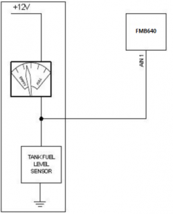 |
| Alarm buttons, door sensors etc. | Panic button connection to FMB640 |
| Alarm buttons, door sensors, ignition, etc. have two output states: high or low. FMB640 Digital inputs are used to detect these states. | 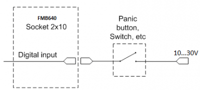 |
| Relays | Inverting relay connection to FMB640 |
| In cases when sensor output signal is negative, an additional relay has to be installed to convert negative signal to positive. | 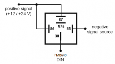 |
| Immobilizer relay | Immobilizer relay connection to FMB640 output |
| When connected as shown on the right hand side, FMB640 disables engine starter when output is ON. | 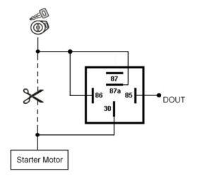 |
| Automotive relay | Automotive relay pinout |
An ordinary automotive relay is used to invert input signal or to immobilize engine starter. Note that relays can be 12 V or 24 V capable.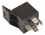 |
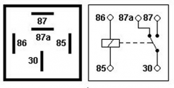 |
| 1-Wire devices | Digital thermometer DS1820 and TTJ100 connection to FMB640 |
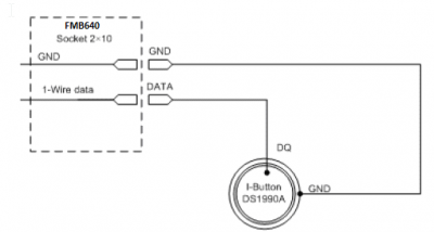
| One of the implemented features on FMB640 is 1-Wire® data protocol, which enables connection to devices such as thermometer (DS1820, DS18S20 and DS18B20) and I-Button DS1990A. | 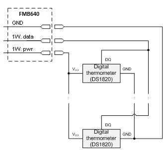 |
| TTJ sensor pinout | |
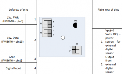 | |
| I-Button DS1990A connection to FMB640 | |
 | |
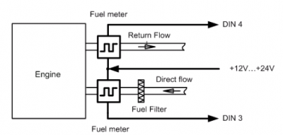
| Impulse counters | Pulse fuel meters connection scheme |
| Here two pulse meters are used, where one is mounted on the direct flow valve and the other on the return flow valve. Data from both meters is sent to the FMB640. Then FMB640 calculates DIN3-DIN4. Resulting difference equals to fuel consumption. Filter should be used on the direct flow pipe to prevent any damage caused by impurities in the liquid. The filter mounted in the meter inlet is only a safety filter and it is too small to act as a strainer. Read more about impulse counters here
|
 |
