FMB225 I/O settings: Difference between revisions
No edit summary |
m Protected "FMB225 I/O settings" ([Edit=Allow only administrators] (indefinite) [Move=Allow only administrators] (indefinite)) |
||
| (One intermediate revision by the same user not shown) | |||
| Line 104: | Line 104: | ||
[[Image:Fmb125_lls_sensors.png|300px|right]] | [[Image:Fmb125_lls_sensors.png|300px|right]] | ||
LLS addresses may be configured for 5 LLS sensors. If at least one LLS sensor is connected to FMB125 when configuring device using configurator, LLS sensor ID will be entered automatically | LLS addresses may be configured for 5 LLS sensors. If at least one LLS sensor is connected to FMB125 when configuring device using configurator, LLS sensor ID will be entered automatically. | ||
[[Category:FMB225 Configuration]] | [[Category:FMB225 Configuration]] | ||
Revision as of 10:39, 28 January 2022
Main Page > Professional Trackers > FMB225 > FMB225 Configuration > FMB225 I/O settingsWhen no I/O element is enabled, AVL packet comes with GNSS information only. After enabling I/O element(s) AVL packet contains current value(s) of enabled I/O element(s) along with GNSS information.
Input Name
I/O element name.
Current Value
If device is connected to Configurator all current I/O values are displayed in this column. Also I/O current values can be seen in Status→I/O Info tab.
Units
Units of measurement.
Priority
This field allows to enable I/O elements and setting them a priority so they are added to the data packet, which is sent to the server. By default 12 I/O elements with Low priority are enabled: Ignition, Movement, Data Mode, GSM Signal, Sleep Mode, GNSS Status, GNSS PDOP, GNSS HDOP, External Voltage, Speed, Battery Current, Battery Voltage. All records made by FMB125 are regular, and regular packets are sent as low priority records.
Priority level (AVL packet priority) can be:
None Priority
Module doesn't make additional record.
Low Priority
Module makes an additional record with an indication that the event was caused by an I/O element change (depending on Operands configuration).
High Priority
Module makes an additional record with High priority flag and sends event packet immediately to the server using GPRS.
Panic Priority
This priority triggers same actions as High priority, but if GPRS fails, it sends an AVL packet using SMS data if SMS data sending is enabled and the number is provided in SMS/Call Settings.
High and Low Level
These levels define I/O value range. If I/O value enters or exits this range, FMB125 generates an event.
Event Only
When this is selected, I/O element status value will be appended only to eventual records, otherwise I/O element status value will appear in each AVL record.
Operands
Defines when to generate event: On Exit, On Entrance, On Both, Monitoring, On Hysteresis, On Change or On Delta Change.
Operand On Exit
Record is generated when input value leaves a range between low and high level limits.

Operand On Entrance
Record is generated when input value enters a range between low and high level limits.
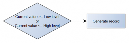
Operand On Both
Record is generated by both On Exit and On Entrance operands' logic at same time.

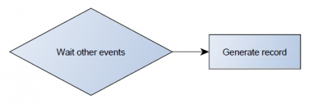
Operand Monitoring
No event at all. Values are recorded only when other triggers worked.
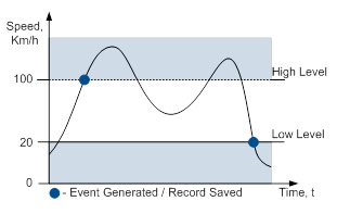
Operand On Hysteresis
Record is generated when input value crosses the high limit value from below the low limit value or vice versa.
Operand On Change
Record is generated when input value changes.

Operand On Delta Change
Record is generated when input value changes and the absolute change becomes equal to or higher than the limit value.

Avg Const
If Avg Const value is 10, new value must be present for 1 second to register the change to a new value. Internal sampling is done every 40 ms, so 25 samples are taken per second. To configure 5 seconds of averaging multiply 10 by 5 yielding 50 as Avg Const value. The same logic works if the device is in Deep Sleep mode.
Averaging follows RC exponential curve, see image below:
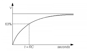
For Boolean values of 5τ, values is used, that means value change is taken when new values is averaged to more than 99.3%.
![]() NOTE: Average Constant is not used as an activation timer or delay timer. But it is used as a filter.
NOTE: Average Constant is not used as an activation timer or delay timer. But it is used as a filter.
Event is generated at different times due to variations in voltage. Average constant is designed to filter jumps instead of event generation time.
For example: generation is set to happen at 14500mV, and actual voltage is set to 15000mV, that record will be generated earlier than 10s with avg const set to 100. This is because avg const is calculating time it takes for device to get to actual voltage (in this case 15000 mV), while device will be generating records when it hits 14500mV.
Send SMS To
Sends SMS notification about event to selected number from SMS/Call Settings GSM Predefined Numbers list if event priority is set to Low, High or Panic.
SMS Text
The SMS Text field can be altered and any text can be entered. Maximum message length is 160 symbols (numbers, letters and symbols in ASCII, except for comma “,”).
SMS Event Text may be either in default or composed format.
Default format:
Date, time, longitude, latitude, 'SMS text', value
Example:
2018/11/02 12:00:00 Lon:0.000000 Lat:0.000000 Alarm 1
Composed format:
Composed format may consist of text and defined commands which start with % symbol.
Supported commands:
| Command | Description |
|---|---|
| imei | IMEI |
| fw | Firmware version |
| fullfw | Full firmware version |
| modem | Modem firmware version |
| gnss | GPS firmware version |
| vin | OBD VIN number |
| lat | Latitude (non-float value) |
| lon | Longitude (non-float value) |
| sat | Satellites in use |
| time | Timestamp |
| din1 | Digital Input 1 |
| din2 | Digital Input 2 |
| din3 | Digital Input 3 |
| ain1 | Analog Input 1 |
| out1 | Digital Output 1 |
| out2 | Digital Output 2 |
| pdp | PDOP |
| hdp | HDOP |
| exv | External Voltage |
| gmap | Google Maps link |
| mov | Movement |
| odo | Trip Odometer |
| op | GSM operator |
| spd | Speed |
| ib | iButton |
| mod | Data Mode |
| sig | GSM signal |
| slp | Sleep Mode |
| cel | Cell ID |
| lac | Area Code |
| tmp | Dallas Temperature 1 |
| mac | BT MAC address |
| dtc | OBD fault codes |
| flat | Latitude (float value) |
| flon | Longitude (float value) |
| date | Date in yyyy/mm/dd format |
| datetime | Time in hh:mm:ss format |
| val | Eventual IO value |
| io'par_id' | Element value by parameter ID |
Composed text example:
%imei Movement %io50010
Event SMS text:
352094082828606 Movement 1
 |
If FMB125 is in Deep Sleep or Ultra Deep Sleep mode and an SMS event occurs with Low priority (which does not wake up FMB125), then the device does not send the message. It is saved to device memory until it wakes up from Deep Sleep or Ultra Deep Sleep mode and GSM modem starts working normally. After it wakes up, all the messages that are saved to memory will be sent, but keep in mind that only 10 messages can be saved to memory – all other messages will not be saved, until there is free memory space. |
FMB125 RS-232/RS-485 parameter configuration
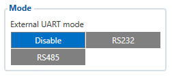
FMB-125 supports RS-232 and RS-485 serial standards and can be configured to work in different RS-232/RS-485 modes. More information about each mode is provided in RS-232 and RS-485.
Only one mode may be selected at a time:
- Disable - Disable RS-232/RS-485 functionality;
- RS232 - Select RS-232 functionality;
- RS485 - Select RS-485 functionality.
RS-232 modes
RS-232 supports following modes:
- Log Mode – suitable for debugging/logging;
- NMEA – NMEA logs are transferred;
- LLS – LLS sensor support;
- LCD – external LCD support;
- RFID HID – RFID HID reader support;
- RFID MF7 - RFID MF7 reader support;
- Garmin FMI – Garmin support;
- TCP ASCII – for routing any input string from external device to the server;
- TCP Binary – for routing any binary input data from external device to the server.
RS-232 baudrate and parity
Every RS-232 mode supports different baudrates, but each mode has its own default baudrate value. Default baudrate and parity values for each RS-232 mode are provided in the table below.
| Mode | Default settings | ||
|---|---|---|---|
| RS-232 | RS-485 | ||
| Baudrate | Parity | Baudrate | |
| Log Mode | 115200 | None | 115200 |
| NMEA | 115200 | 115200 | |
| LLS | 19200 | 19200 | |
| LCD | 57600 | - | |
| RFID HID | 57600 | - | |
| RFID MF7 | 9600 | - | |
| Garmin FMI | 9600 | - | |
| TCP ASCII | 115200 | 57600 | |
| TCP Binary | 115200 | 57600 | |
RS-232 TCP Binary mode settings
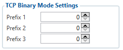
RS-232 TCP Binary mode has additional configurable parameters for advanced data filtering as shown on the right hand side figure.
RS-232 Garmin mode settings

Garmin FMI mode has addditional filtering capabilities. It is possible to filter Ping and Unicode packets. If Ping Filter is enabled, then Ping packets are blocked. When Unicode Filter is enabled Unicode packets are not sent to the server. Both filters may be enabled for simultaneous effect.
RS-485 modes
RS-485 supports several modes:
- Log Mode – suitable for debugging/logging;
- NMEA – NMEA logs are transferred;
- LLS – LLS sensors support;
- TCP ASCII – for routing any input string from external device to the server;
- TCP Binary – for routing any binary input data from external device to the server.
RS-485 baudrate
Every RS-485 mode supports different baudrates, but each mode has its own default baudrate value. Default baudrate values for each RS-485 mode are provided in the table above.
RS-485 LLS sensors
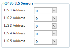
LLS addresses may be configured for 5 LLS sensors. If at least one LLS sensor is connected to FMB125 when configuring device using configurator, LLS sensor ID will be entered automatically.
