Difference between revisions of "Template:FMM640 Short burst data settings"
(No difference)
| |
Latest revision as of 16:19, 14 November 2022
Short burst data settings
supports Iridium devices which can send short burst data (SBD) to the server. This means that some data can be sent from FM device to the server through satellites.
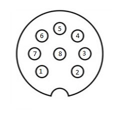
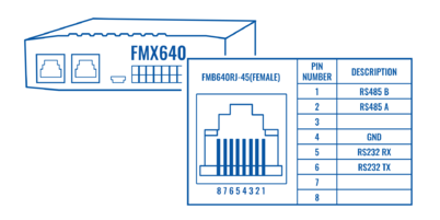
In order to properly connect the Iridium device to , Iridium has to be connected to the device via RS-232 - COM1 or COM2 (with RJ-45 connector, where 4 pin is GND, 5 pin is RS232 Rx and 6 PIN is RS232 Tx). Additionally Pin No. 6 - power control (reference in the image below) must be connected to one of the DOUTs (1/2/3/4), in order to allow the device to power ON/OFF Iridium device on demand. More information about SBD can be found here Short Burst Data.
Iridium Edge pinout and RS232 COM 1/2 connection:
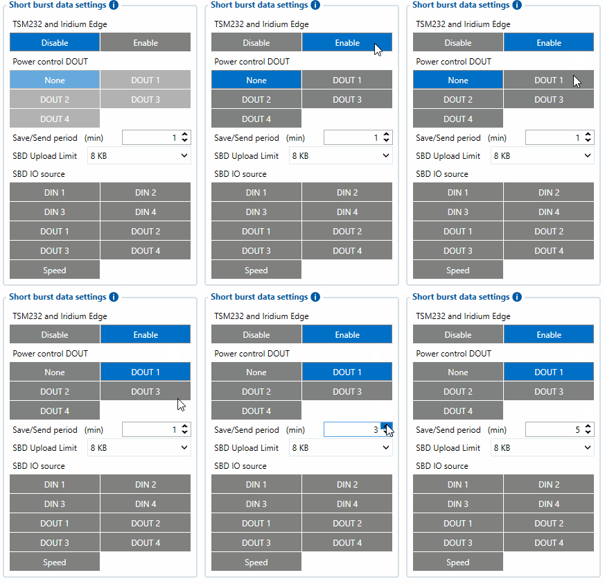
When the Iridium edge device is connected Power control DOUT configures DOUT pin which can control Iridium Edge ON/OFF pin. Configure if DOUT pin is connected. Respective power control DOUT to which the Iridium device's PIN6 is connected must be selected.
Save/Send period configures how long will FMB device wait after losing the signal to generate SBD packet. If the signal is not recovered, it will send it indefinitely (or till the SBD Upload limit is reached, if such is set).
SBD Upload Limit is configurable and resets every month. This option can ensure that no additional data is used so that no unexpected costs are experienced by the customer. The default value is 8000 (for 8KB plan). This option can be disabled by setting the Upload limit to 0. The monthly data usage counter can be reset by using the SMS/GPRS command - sbdlimitsreset.
SBD IO source configures IO source which can trigger SBD record saving. 9 elements can generate an Alarm for SDB sending. These elements are:
- Digital input 1
- Digital input 2
- Digital input 3
- Digital input 4
- Digital output 1
- Digital output 2
- Digital output 3
- Digital output 4
- Speed
Configurator parameter IDs and their explanation:
| Parameter ID |
Parameter name | Values | Explanation | ||
|---|---|---|---|---|---|
| Min | Max | Default | |||
| 99420 | Iridium Edge | 0 | 1 | 0 | This parameter enables or disables Iridium Edge functionality |
| 99421 | Save/Send period | 0 | 1440 | 1440 | This parameter lets to configure Iridium Edge sending period |
| 99422 | SBD IO source* | 0 | 8 | 0 | SBD IO elements which when enabled are included into the SBD record |
| 99423 | SBD UploadLimit | 0 | 30000 | 8000 | Limit to save user from exceeding the monthly plan. Max limit of 30000 due to 30KB plan. If set to 0 – limit will be off. |
| 99424 | Power control DOUT | 1 | 5 | 0 | Device DOUT which can control ON/OFF pin of the Iridium Edge |
| 151 | RS232 Mode | 0 | 23 | 0 | RS-232 mode selection. "Satellite backup" - 15 |
* SBD IO source parameter is configured with bitmasks:
- eSBD_IO_Bit_Disabled = 0x00,
- eSBD_IO_Bit_Din1 = 0x01,
- eSBD_IO_Bit_Din2 = 0x02,
- eSBD_IO_Bit_Din3 = 0x04,
- eSBD_IO_Bit_Din4 = 0x08,
- eSBD_IO_Bit_Do1 = 0x10,
- eSBD_IO_Bit_Do2 = 0x20,
- eSBD_IO_Bit_Do3 = 0x40,
- eSBD_IO_Bit_Do4 = 0x80,
- eSBD_IO_Bit_Speed = 0x100
For example: to enable Din1, Din3 and Do4: 0x01 + 0x04 + 0x80 = 0x85 convert to decimal --> 133.


