Difference between revisions of "Template:FMB64 First start card"
| (18 intermediate revisions by 8 users not shown) | |||
| Line 2: | Line 2: | ||
| − | <b>{{{description|Leading GNSS/ | + | <b>{{{description|Leading LTE/GNSS/BLE Terminal for advanced applications}}}</b> |
| − | {{{pic|[[Image: | + | {{{pic|[[Image:FMB640_600X600_1.png|400px|right]]}}} |
| + | |||
| Line 9: | Line 10: | ||
| − | =='''How to insert {{{ | + | =='''How to insert SIM card {{{battery|and connect the battery}}}'''== |
| − | # Unscrew the ''' | + | # '''Unscrew''' 4 screws counterclockwise that are located on the '''bottom''' of the device. |
| − | # | + | # Remove the '''cover'''. |
| − | # Insert ''' | + | # Insert '''SIM''' card as shown with '''PIN request disabled''' or read '''[[{{{model|FMB640}}} Security info|Security info]]''' how to enter it later in [[Teltonika Configurator]]. Make sure that SIM card '''cut-off corner''' is pointing outwards. {{{dual_sim|'''SIM slot 1''' is closer to PCB, '''SIM slot 2''' is the upper one.}}} |
| − | # | + | {{{be_battery|# Connect '''battery''' as shown to device.}}} |
| − | # | + | # After '''configuration''', see “'''[[{{{model|FMB640}}}_First_Start#PC Connection (Windows)|PC Connection (Windows)]]'''”, attach device '''cover''' back. |
| − | + | # '''Screw''' in all screws. Device is ready to be mounted. | |
| − | [[Image:1 | + | [[Image:{{{sim_insert_pic1|{{{model|Fmb640}}}-cover-1.png}}}|260px]][[Image:{{{sim_insert_pic2|{{{model|Fmb640}}}-cover-2.png}}}|260px]][[Image:{{{sim_insert_pic3|{{{model|Fmb640}}}-cover-3.png}}}|260px]][[Image:{{{sim_insert_pic4|{{{model|Fmb640}}}-cover-4.png}}}|260px]][[Image:{{{sim_insert_pic4|{{{model|Fmb640}}}-cover-5.png}}}|260px]][[Image:{{{sim_insert_pic4|{{{model|Fmb640}}}-cover-6.png}}}|260px]] |
| − | [[Image: | ||
| − | + | [[File:Alert.png|left|link=]] <br> <b>{{{sim_type|Micro-}}}SIM card insertion/removal must be performed when device is powered off – external voltage {{{battery|and internal battery}}} disconnected. Otherwise {{{sim_type|Micro-}}}SIM card might be damaged or device will not detect it.</b><br> | |
| − | |||
| − | |||
| − | |||
| − | + | [[File:SIM_3in1.png|left|230px]] <b>FMX6 devices use Standard size SIM cards for SIM1 and SIM2. Currently most of the SIM cards provided by operators can be disassembled into 3 parts - Standard/Micro/Nano. Depending on the SIM card construction - during device usage in harsh conditions, SIM assembly might come apart which causes instability when connecting to operator.<br> | |
| + | To avoid such risk:<br> | ||
| + | 1) If possible - ask operator for Standard SIM card with solid construction (not pre-cut to 3 parts) <br> | ||
| + | 2) Do not use SIM cards that were previously disassembled (SIM was taken apart previously)<br> | ||
| + | 3) If you plan to use only one SIM card - insert it into SIM1 slot (lower slot) - this ensures greater pressure on SIM contacts as the contact bed is pushed by PCB.<br> | ||
| + | When 2 SIM cards are used simultaneously risk is mitigated as well - when SIM1 is inserted, a greater pressure is applied for SIM2, so SIM parts are harder to come lose </b><br> | ||
| + | <br> | ||
| + | <br> | ||
| + | <br> | ||
| + | =='''How to insert microSD card into {{{model|FMB640}}}'''== | ||
| + | <br> | ||
| + | [[File:Micro sd insert V1.2.gif|500px|right]] | ||
# Push microSD card lock case. | # Push microSD card lock case. | ||
# Open microSD card locker. | # Open microSD card locker. | ||
| Line 34: | Line 42: | ||
# Close microSD card locker. | # Close microSD card locker. | ||
# Push microSD card lock case to locked position. | # Push microSD card lock case to locked position. | ||
| − | + | <br> | |
| − | |||
Latest revision as of 10:37, 12 April 2023
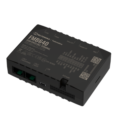
Leading LTE/GNSS/BLE Terminal for advanced applications
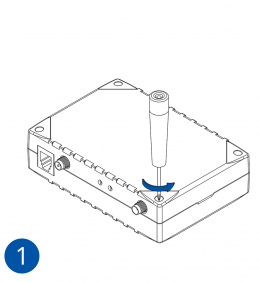
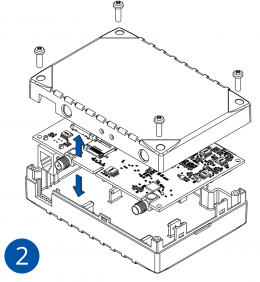
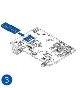
How to insert SIM card and connect the battery
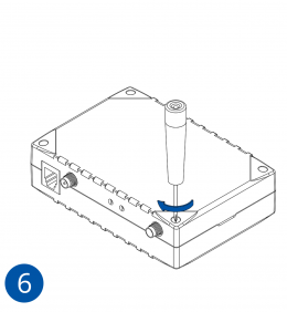
- Unscrew 4 screws counterclockwise that are located on the bottom of the device.
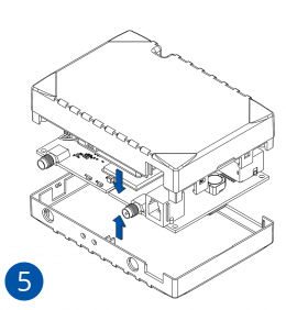
- Remove the cover.
- Insert SIM card as shown with PIN request disabled or read Security info how to enter it later in Teltonika Configurator. Make sure that SIM card cut-off corner is pointing outwards. SIM slot 1 is closer to PCB, SIM slot 2 is the upper one.
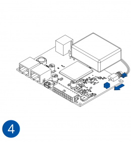
- Connect battery as shown to device.
- After configuration, see “PC Connection (Windows)”, attach device cover back.
- Screw in all screws. Device is ready to be mounted.

Micro-SIM card insertion/removal must be performed when device is powered off – external voltage and internal battery disconnected. Otherwise Micro-SIM card might be damaged or device will not detect it.
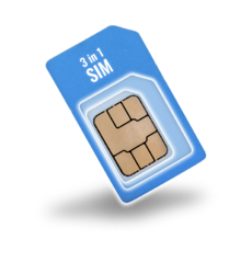
FMX6 devices use Standard size SIM cards for SIM1 and SIM2. Currently most of the SIM cards provided by operators can be disassembled into 3 parts - Standard/Micro/Nano. Depending on the SIM card construction - during device usage in harsh conditions, SIM assembly might come apart which causes instability when connecting to operator.
To avoid such risk:
1) If possible - ask operator for Standard SIM card with solid construction (not pre-cut to 3 parts)
2) Do not use SIM cards that were previously disassembled (SIM was taken apart previously)
3) If you plan to use only one SIM card - insert it into SIM1 slot (lower slot) - this ensures greater pressure on SIM contacts as the contact bed is pushed by PCB.
When 2 SIM cards are used simultaneously risk is mitigated as well - when SIM1 is inserted, a greater pressure is applied for SIM2, so SIM parts are harder to come lose
How to insert microSD card into FMB640
- Push microSD card lock case.
- Open microSD card locker.
- Correctly insert microSD card into slot.
- Close microSD card locker.
- Push microSD card lock case to locked position.

