FM63XX/FMB630 and FMB640 and Tachograph Solution: Difference between revisions
No edit summary |
No edit summary |
||
| (One intermediate revision by one other user not shown) | |||
| Line 24: | Line 24: | ||
Supported devices are: Siemens VDO Digital Tachograph – DTCO 1381 (release 1.3a, 1.4 | Supported devices are: Siemens VDO Digital Tachograph – DTCO 1381 (release 1.3a, 1.4 | ||
or later) and Stoneridge Tachograph – SE5000 (release 7.1 or later). Version can be checked on | or later) and Stoneridge Tachograph – SE5000 (release 7.1 or later). Version can be checked on | ||
tachograph or in cheque as shown in pictures below | tachograph or in cheque as shown in pictures below: | ||
[[Image:Tacho_version.PNG|800px|center]] | |||
[[Image:Tacho_version_1.PNG|800px|center]] | |||
==CONNECTING TO TACHOGRAPH== | ==CONNECTING TO TACHOGRAPH== | ||
[[Image:Tacho_connection.PNG|800px|center]] | |||
<br /> | <br /> | ||
<big>Before connecting tachograph wires, it is required to measure CAN line resistance | <big>Before connecting tachograph wires, it is required to measure CAN line resistance | ||
| Line 47: | Line 51: | ||
• All of the same level CAN-L and CAN-H wires must be interlaced with each other.<br /> | • All of the same level CAN-L and CAN-H wires must be interlaced with each other.<br /> | ||
[[Image:Wires.PNG|800px|center]] | |||
• CAN wires need to be installed as far as possible from GSM antenna.<br /> | • CAN wires need to be installed as far as possible from GSM antenna.<br /> | ||
Below is wiring diagram of Tachograph and FM6400/FMB640 device | <big>Below is wiring diagram of Tachograph and FM6400/FMB640 device:</big><br /> | ||
[[Image:Wiring_diagram.PNG|800px|center]] | |||
| Line 85: | Line 93: | ||
''' | ''' | ||
==CONFIGURING DEVICE== | ==CONFIGURING DEVICE== | ||
'''In FMB640 configurator “CAN/Tachograph” section tachograph settings should be set in order to download files.<br />''' | |||
<br /> | |||
DDD download source – to which CAN line tachograph is connected;<br /> | |||
Tachograph ignition source – which DIN is connected to vehicle ignition ("Ignition" parameter - tachograph ignition source will be the same as configured in "System" -> "Ignition Source");<br /> | |||
WEB Tacho Settings:<br /> | |||
Status - functionality enabling;<br /> | |||
Domain – server domain where files will be send;<br /> | |||
Port – server port where files will be send;<br /> | |||
Start delay – delay after turning on ignition to start procedure of file sending.<br /> | |||
[[Image:Configuration_tacho1111.PNG|800px|center]] | |||
==External links== | ==External links== | ||
https://teltonika.lt/product/tachograph-web/ <br /> | |||
https://teltonika. | https://wiki.teltonika-gps.com/view/FMB640 | ||
Latest revision as of 13:27, 24 February 2022
INTRODUCTION
Teltonika Tachograph Solution is a big
forward leap in remote tachograph data files download. Solution is easily manageable and does
not require any complex software* installation. Everything is accessible via web page. Now you
can download tachograph files from any place and from any PC via internet access.
FMB640 device has a possibility to connect to Web Tacho IP every 1 hour and check if there
are any schedules for downloading DDD files. If FMB640 connects to Web tacho server, and there
is a planned schedule but other device is already downloading and company card is in use, device
keeps link with Web Tacho server but still sends data to main server with AVL data. After
successful download, device closes link with Web Tacho and reconnects after 1 hour. Data is
stored on secured server and can be accessed only by your authorized users. You don't need to
worry that any file is lost and you have to download is from tachograph once again.
*- requires company card reader software installation on a single company PC
SUPPORTED TACHOGRAPHS AND FORMATS
Solution supports not only the standard DDD file extension, but also Spanish TGD and French V1B, C1B file formats. You simply set required one in Web Tacho user settings.
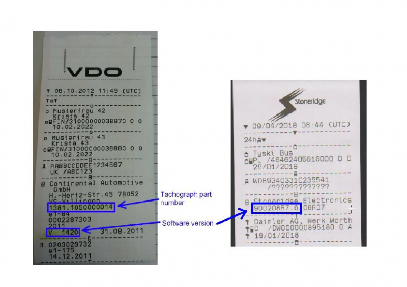
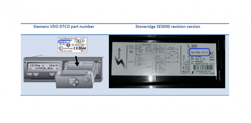
Supported devices are: Siemens VDO Digital Tachograph – DTCO 1381 (release 1.3a, 1.4 or later) and Stoneridge Tachograph – SE5000 (release 7.1 or later). Version can be checked on tachograph or in cheque as shown in pictures below:
CONNECTING TO TACHOGRAPH
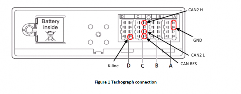
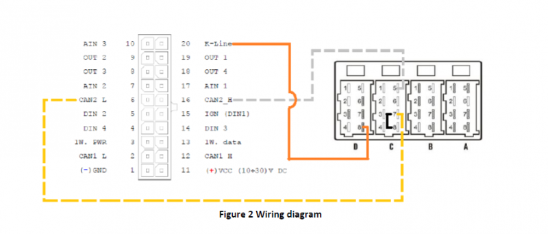
Before connecting tachograph wires, it is required to measure CAN line resistance
while tachograph is switched off:
1. Turn off the vehicle ignition;
2. Measure resistance between the C5 (CAN2 H) and C7 (CAN2 L) contacts;
3. If the multimeter shows ~120 Ohms, skip the next step;
4. If the multimeter shows kilo Ohms resistance then it is needed to connect tachograph C8 (CAN-RES) and C7 (CAN2 L) contacts with wire and then perform further actions;
5. Re-measure the resistance of the line – it has to be ~120 Ohms.
6. Connect CAN2 L and CAN2 H wires to tachograph (C5 (CAN2 H) and C7 (CAN2 L))
• All of the same level CAN-L and CAN-H wires must be interlaced with each other.

• CAN wires need to be installed as far as possible from GSM antenna.
Below is wiring diagram of Tachograph and FM6400/FMB640 device:
CHECKING CONNECTION (TACHOCHECK SMS)
After successful connection “tachocheck” sms message can be sent to device for checking if
data presented on connected lines, by another words if connections were done correctly. It is
used for getting status information. SMS response is of such structure:
CAN_2:[TRC],[ABCD], K-Line:[K]
[T] – Tachograph presence on bus:
 • 0 – Tachograph doesn’t respond on bus;
 • 1 – Tachograph responds on bus.
[R] – Response to Open Remote Session validity check:
 • 0 – Wrong or unknown response (failed to open Remote Session);
 • 1 – Tachograph responds positively (Remote Session opened successfully).
[C] – Response to Close Last Authentication Session validity check:
 • 0 – Wrong or unknown response (failed to close last authentication session);
 • 1 – Last authentication session closed successfully, device is ready to open new authentication session.
[K] – K-Line data presence on bus:
 • 0 – K-Line data not present on bus;
 • 1 – K-Line data present on bus. 7 [ABCD] – FMS data presence on bus:
• 0000 – FMS data not present on bus
• Non-zero – FMS data detected on bus.
SMS answer which shows correct line connections looks like “CAN_2:[111],[ABCD], K-Line:[K]”. Such SMS answer means DDD files can be downloaded from tachograph.
CONFIGURING DEVICE
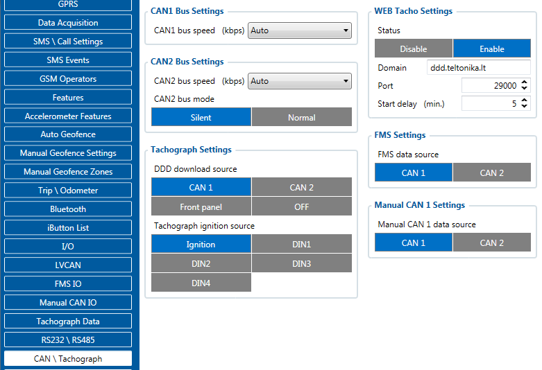
In FMB640 configurator “CAN/Tachograph” section tachograph settings should be set in order to download files.
DDD download source – to which CAN line tachograph is connected;
Tachograph ignition source – which DIN is connected to vehicle ignition ("Ignition" parameter - tachograph ignition source will be the same as configured in "System" -> "Ignition Source");
WEB Tacho Settings:
Status - functionality enabling;
Domain – server domain where files will be send;
Port – server port where files will be send;
Start delay – delay after turning on ignition to start procedure of file sending.
