Difference between revisions of "FMB202 First Start"
| (2 intermediate revisions by 2 users not shown) | |||
| Line 1: | Line 1: | ||
| − | {{Template:FMB2_First_start_card|model=FMB202|antenna=GNSS/GSM antennas|pic=[[Image:FMB202 | + | {{Template:FMB2_First_start_card|model=FMB202|antenna=GNSS/GSM antennas|pic=[[Image:FMB202-side-2023-12-29.png|600px|right]]|family=FMB2}} |
{{Template:FMB First start config|model=FMB202|config_link=[[FMB202 Configuration|here]]|cfg_connect=Configurator_connect-FMB202.jpg|dc_voltage=6-30 V|led_status_link=[[FMB202 LED status]]|power_cable=power cable|family=FMB2}} | {{Template:FMB First start config|model=FMB202|config_link=[[FMB202 Configuration|here]]|cfg_connect=Configurator_connect-FMB202.jpg|dc_voltage=6-30 V|led_status_link=[[FMB202 LED status]]|power_cable=power cable|family=FMB2}} | ||
| Line 5: | Line 5: | ||
{{Template:Mounting_recommendations | {{Template:Mounting_recommendations | ||
|plugged_in= | |plugged_in= | ||
| − | |voltage={{{voltage|+6..+30}}} | + | |voltage={{{voltage|+6...+30}}} |
|model=FMB202 | |model=FMB202 | ||
|1x5_connection= | |1x5_connection= | ||
Latest revision as of 13:58, 25 January 2024
Main Page > Advanced Trackers > FMB202 > FMB202 First Start
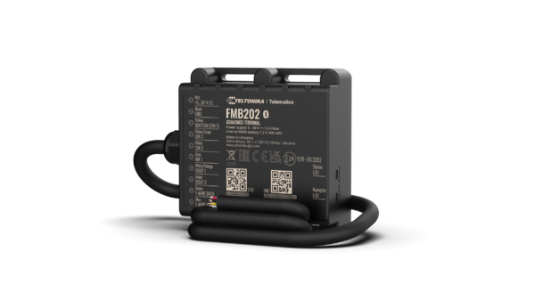
FMB202 Small and professional waterproof tracker with high gain internal GNSS/GSM antennas, Bluetooth and high capacity internal Ni-MH battery
How to insert Micro-SIM card
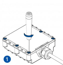
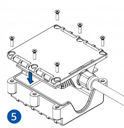
- Unscrew 6 screws counter-clockwise that are located on the bottom of the device.
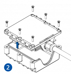
- Remove the cover.
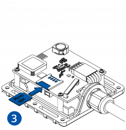
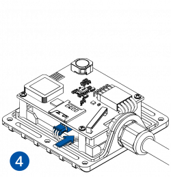
- Insert Micro-SIM card as shown with PIN request disabled or read Security info how to enter it later in Configurator. Make sure that Micro-SIM card cut-off corner is pointing forward to slot.
- Connect battery as shown to device.
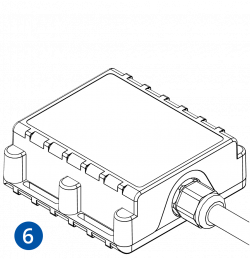
- After configuration, attach device cover and put the screws back in.
- Device is ready to be connected.
 |
Micro-SIM card insertion/removal must be performed when device is powered off – external voltage and battery are disconnected. Otherwise Micro-SIM card might be damaged or device will not detect it. |
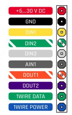
Cable colors
| PIN NUMBER | PIN NAME | DESCRIPTION | |
|---|---|---|---|
| Red | VCC (6-30)V DC (+) | Power supply (+6...30 V DC). | |
| Black | GND (-) | Ground. | |
| Yellow | DIN 1 | Digital input, channel 1. | |
| White/Green | DIN 2 | Digital input, channel 2. | |
| White | DIN 3 | Digital input, channel 3. | |
| Grey | AIN 1 | Analog input, channel 1. Input range: 0-30 V DC. | |
| White/Orange | DOUT 1 | Digital output, channel 1. Open collector output. Max. 3,3 A DC. | |
| Violet | DOUT 2 | Digital output, channel 2. Open collector output. Max. 3,3 A DC. | |
| Green | 1WIRE DATA | Data channel for 1–Wire devices. | |
| Blue | 1WIRE POWER | +3,8 V output for 1–Wire devices. |
PC Connection (Windows)
- Power-up FMB202 with DC voltage 6-30 V power supply using power cable. LED’s should start blinking, see “FMB202 LED status”.
- Connect device to computer using Micro-USB cable or Bluetooth® connection:
- Using Micro-USB cable
- You will need to install USB drivers, see "How to install USB drivers (Windows)"
- Using Bluetooth®
- FMB202 Bluetooth® is enabled by default. Turn on Bluetooth® on your PC, then select Add Bluetooth® or other device > Bluetooth®. Choose your device named – “FMB202_last_7_imei_digits”, without LE in the end. Enter default password 5555, press Connect and then select Done.
- Using Micro-USB cable
- You are now ready to use the device on your computer.
How to install USB drivers (Windows)
- Please download COM port drivers from here.
- Extract and run TeltonikaCOMDriver.exe.
- Click Next in driver installation window.
- In the following window click Install button.
- Setup will continue installing the driver and eventually the confirmation window will appear. Click Finish to complete the setup.
Configuration (Windows)
At first FMB202 device will have default factory settings set. These settings should be changed according to the user's needs.
Main configuration can be performed via Teltonika Configurator software. Get the latest FMB202 Configurator version from here. Configurator operates on Microsoft Windows OS and uses prerequisite MS .NET Framework. Make sure you have the correct version installed.
| MS .NET requirements | |||
|---|---|---|---|
| Operating system | MS .NET Framework version | Version | Link |
|
MS .NET Framework 5.0 | 32 and 64 bit | .NET Framework |
Downloaded Configurator will be in compressed archive. Extract it and launch Configurator.exe. After launch software language can be changed by clicking ![]() in the right bottom corner:
in the right bottom corner:
Configuration process begins by pressing on connected device:
After connection to Configurator Status window will be displayed:
Various Status window tabs display information about GNSS, GSM, I/O, Maintenance and etc. FMB202 has one user editable profile, which can be loaded and saved to the device. After any modification of configuration the changes need to be saved to device using Save to device button. Main buttons offer following functionality:
 Load from device – loads configuration from device.
 Save to device – saves configuration to device.
 Load from file – loads configuration from file.
 Save to file – saves configuration to file.
 Update firmware – updates firmware on device.
 Read records – read records from device.
 Reboot device – restarts device.
 Reset configuration – sets device configuration to default.
Most important configurator section is GPRS – where all your server and GPRS settings can be configured and Data Acquisition – where data acquiring parameters can be configured. More details about FMB202 configuration using Configurator can be found here.
Quick SMS configuration
Default configuration has optimal parameters present to ensure best performance of track quality and data usage.
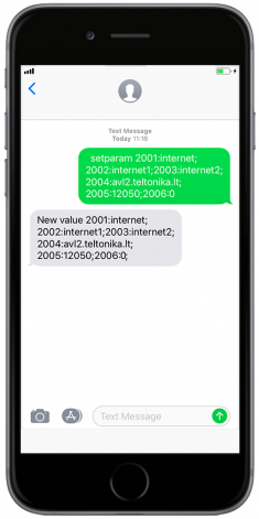
Quickly set up your device by sending this SMS command to it:
" setparam 2001:APN;2002:APN_username;2003:APN_password;2004:Domain;2005:Port;2006:0"
GPRS settings:
- 2001 – APN
- 2002 – APN username (if there are no APN username, empty field should be left)
- 2003 – APN password (if there are no APN password, empty field should be left)
Server settings:
- 2004 – Domain
- 2005 – Port
- 2006 – Data sending protocol (0 – TCP, 1 – UDP)
Note: Before SMS text, two space symbols should be inserted.
After successful SMS configuration, FMB202 device will synchronize time and update records to configured server. Time intervals and default I/O elements can be changed by using Teltonika Configurator or SMS parameters.
Mounting recommendations
- Connecting wires
- Wires should be fastened to stable wires or other non-moving parts. Any heat emitting and/or moving objects should be kept away from the wires.
- There should be no exposed wires. If factory isolation was removed while connecting wires, the isolation material should be applied.
- If the wires are placed in the exterior or in places where they can be damaged or exposed to heat, humidity, dirt, etc., additional isolation should be applied and the wires should not be loose.
- Wires cannot be connected to the board computers or control units.
- Connecting power source
- Be sure that after the car computer goes to sleep mode, power might be still available on the power wires. Depending on car, this may happen in 5 to 30 minutes period.
- When module is connected, measure voltage again to make sure it did not decrease.
- It is recommended to connect to the main power cable in the fuse box.
- 3 A, 125 V external fuse shall be used.
- Connecting ignition wire
- Be sure to check if it is a real ignition wire i. e. power does not disappear after starting the engine.
- Check if this is not an ACC wire (when key is in the first position, most of the vehicle electronics are available).
- Check if power is still available when you turn off any of vehicles devices.
- Ignition is connected to the ignition relay output. As alternative, any other relay, which has power output when ignition is on, may be chosen.
- Connecting ground wire
- Ground wire is connected to the vehicle frame or metal parts that are fixed to the frame.
- If the wire is fixed with the bolt, the loop must be connected to the end of the wire.
- For better contact scrub paint from the spot where loop is going to be connected.
 |
PAY ATTENTION! Connecting the power supply must be carried out in a very low impedance point of on-board vehicle network. These points in the car are the battery terminals. Therefore, we recommend connecting the power of FMB202 (GND and POWER wires) directly to the battery terminals. Another valid option is to connect the wires to the main POWER cable inside the fuse box (if there is none, then to the power supply where the fuses of vehicle’s computer are), GND wire must be connected in a special point, designed to connect GND vehicle computer. Connecting the GND at an arbitrary point to the mass of the car is unacceptable, as static and dynamic potentials on the line GND will be unpredictable, which can lead to unstable FMB202 operation and even its failure. |
Installation instructions
FMB202 is the device that has internal GNSS and GSM antenna.
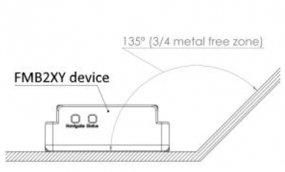
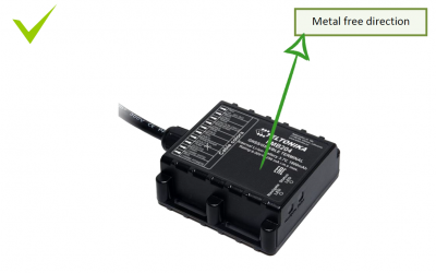
Internal GNSS antenna device should be mounted with the sticker view to the open sky
(metal free) with not less than ¾ of metal free area as shown in figure below.
FMB202 has IP67 protection class. Top performance is reached if mounted outside of the
vehicle.
The device has 4 mounting holes on the edges, and can be tightened with screws, adhesive
tape or plastic straps.
FMB202 area with sticker and GNSS antenna is shown in figure below.
Safety information
This message contains information on how to operate FMB202 safely. By following these requirements and recommendations, you will avoid dangerous situations. You must read these instructions carefully and follow them strictly before operating the device!
- The device uses SELV limited power source. The nominal voltage is +12 V DC. The allowed voltage range is +6...+30V DC.
- To avoid mechanical damage, it is advised to transport the device in an impact-proof package. Before usage, the device should be placed so that its LED indicators are visible. They show the status of device operation.
- When connecting the wires, the appropriate jumpers of the vehicle power supply should be disconnected.
- When installing the connection cables to the vehicle, the appropriate jumpers of the power supply of the vehicle should be disconnected.
- Before unmounting the device from the vehicle, the must be disconnected.
- The device is designed to be mounted in a zone of limited access, which is inaccessible to the operator. All related devices must meet the requirements of EN 60950-1 standard.
- The device FMB202 is not designed as a navigational device for boats.
Precautions

