UL202 Ultrasonic Fuel Sensor: Difference between revisions
No edit summary |
No edit summary |
||
| (2 intermediate revisions by one other user not shown) | |||
| Line 4: | Line 4: | ||
'''UL202''' <br> | '''UL202''' <br> | ||
{| class="wikitable" | |||
|+ | |||
! style="width:30%; border: 1px solid white; border-bottom: 2px solid #0054A6; background: white; color: #0054A6; text-align: left;" |Color | |||
! style="border: 1px solid white; border-bottom: 2px solid #0054A6; background: white; color: #0054A6; text-align: left;" |Definition of LED light | |||
|- | |||
| style="border: 1px solid white; border-bottom: 2px solid #E8E8E8; text-align: left; vertical-align: center; background: white;" |<span style="color:green"><b>Green</b></span> light | |||
| style="border: 1px solid white; border-bottom: 2px solid #E8E8E8; text-align: left; vertical-align: center; background: white;" |the probe works normally | |||
|- | |||
| style="border: 1px solid white; border-bottom: 2px solid #E8E8E8; text-align: left; vertical-align: center; background: white;" |<span style="color:red"><b>Red</b></span> light | |||
| style="border: 1px solid white; border-bottom: 2px solid #E8E8E8; text-align: left; vertical-align: center; background: white;" |the probe is abnormal (the probe line is not inserted or probe drops off) | |||
|- | |||
|} | |||
[[image:Ul202-2.png|400px]] <br> | [[image:Ul202-2.png|400px]] <br> | ||
'''Ul202 sensor technical parameters:''' <br> | '''Ul202 sensor technical parameters:''' <br> | ||
{| class="wikitable" | |||
|+ | |||
! style="width:30%; border: 1px solid white; border-bottom: 2px solid #0054A6; background: white; color: #0054A6; text-align: left;" |Description | |||
! style="border: 1px solid white; border-bottom: 2px solid #0054A6; background: white; color: #0054A6; text-align: left;" |Physical Specification | |||
|- | |||
| style="border: 1px solid white; border-bottom: 2px solid #E8E8E8; text-align: left; vertical-align: center; background: white;" |Operating voltage | |||
| style="border: 1px solid white; border-bottom: 2px solid #E8E8E8; text-align: left; vertical-align: center; background: white;" |9-36VDC | |||
|- | |||
| style="border: 1px solid white; border-bottom: 2px solid #E8E8E8; text-align: left; vertical-align: center; background: white;" |Maximum power consumption | |||
| style="border: 1px solid white; border-bottom: 2px solid #E8E8E8; text-align: left; vertical-align: center; background: white;" |0.8W/12VDC | |||
|- | |||
| style="border: 1px solid white; border-bottom: 2px solid #E8E8E8; text-align: left; vertical-align: center; background: white;" |Work temperature | |||
| style="border: 1px solid white; border-bottom: 2px solid #E8E8E8; text-align: left; vertical-align: center; background: white;" | -40°C - +85°C | |||
|- | |||
| style="border: 1px solid white; border-bottom: 2px solid #E8E8E8; text-align: left; vertical-align: center; background: white;" |Measurement range | |||
| style="border: 1px solid white; border-bottom: 2px solid #E8E8E8; text-align: left; vertical-align: center; background: white;" |Determined according to materials and thickness of the container | |||
|- | |||
| style="border: 1px solid white; border-bottom: 2px solid #E8E8E8; text-align: left; vertical-align: center; background: white;" |Pressure bearing scope | |||
| style="border: 1px solid white; border-bottom: 2px solid #E8E8E8; text-align: left; vertical-align: center; background: white;" |<0.8kg or 0.8MPa | |||
|- | |||
| style="border: 1px solid white; border-bottom: 2px solid #E8E8E8; text-align: left; vertical-align: center; background: white;" |Liquid measurement accuracy | |||
| style="border: 1px solid white; border-bottom: 2px solid #E8E8E8; text-align: left; vertical-align: center; background: white;" |+-0.5% | |||
|- | |||
| style="border: 1px solid white; border-bottom: 2px solid #E8E8E8; text-align: left; vertical-align: center; background: white;" |Equipment interface | |||
| style="border: 1px solid white; border-bottom: 2px solid #E8E8E8; text-align: left; vertical-align: center; background: white;" |Provided output port of RS232 | |||
|- | |||
|} | |||
'''Port definition of user interface''' - User interface port is used to connect '''UL202 Ultrasonic Fuel Level Sensor''' connected to FMB640 using with RS232 interface <br> | '''Port definition of user interface''' - User interface port is used to connect '''UL202 Ultrasonic Fuel Level Sensor''' connected to FMB640 using with RS232 interface <br> | ||
| Line 60: | Line 52: | ||
'''Port definition''' <br> | '''Port definition''' <br> | ||
{| class="wikitable" | |||
|+ | |||
! style="width:5%; border: 1px solid white; border-bottom: 2px solid #0054A6; background: white; color: #0054A6; text-align: left;" |PIN Position Nr. | |||
! style="width:10%; border: 1px solid white; border-bottom: 2px solid #0054A6; background: white; color: #0054A6; text-align: left;" |Function | |||
! style="width:10%; border: 1px solid white; border-bottom: 2px solid #0054A6; background: white; color: #0054A6; text-align: left;" |Description | |||
! style="width:10%; border: 1px solid white; border-bottom: 2px solid #0054A6; background: white; color: #0054A6; text-align: left;" |Color | |||
|- | |||
| style="border: 1px solid white; border-bottom: 2px solid #E8E8E8; text-align: left; vertical-align: center; background: white;" |1 | |||
| style="border: 1px solid white; border-bottom: 2px solid #E8E8E8; text-align: left; vertical-align: center; background: white;" |Positive pole of Power supply | |||
| style="border: 1px solid white; border-bottom: 2px solid #E8E8E8; text-align: left; vertical-align: center; background: white;" |9-36VDC | |||
| style="border: 1px solid white; border-bottom: 2px solid #E8E8E8; text-align: left; vertical-align: center; background: white;" |<span style="color:red"><b>Red</b></span> | |||
|- | |||
| style="border: 1px solid white; border-bottom: 2px solid #E8E8E8; text-align: left; vertical-align: center; background: white;" |2 | |||
| style="border: 1px solid white; border-bottom: 2px solid #E8E8E8; text-align: left; vertical-align: center; background: white;" |Negative pole of Power supply | |||
| style="border: 1px solid white; border-bottom: 2px solid #E8E8E8; text-align: left; vertical-align: center; background: white;" |- | |||
| style="border: 1px solid white; border-bottom: 2px solid #E8E8E8; text-align: left; vertical-align: center; background: white;" |<span style="color:black"><b>Black</b></span> | |||
|- | |||
| style="border: 1px solid white; border-bottom: 2px solid #E8E8E8; text-align: left; vertical-align: center; background: white;" |3 | |||
| style="border: 1px solid white; border-bottom: 2px solid #E8E8E8; text-align: left; vertical-align: center; background: white;" |RS232 TX | |||
| style="border: 1px solid white; border-bottom: 2px solid #E8E8E8; text-align: left; vertical-align: center; background: white;" |RS232 transmitting terminal | |||
| style="border: 1px solid white; border-bottom: 2px solid #E8E8E8; text-align: left; vertical-align: center; background: white;" |<span style="color:yellow"><b>Yellow</b></span> | |||
|- | |||
| style="border: 1px solid white; border-bottom: 2px solid #E8E8E8; text-align: left; vertical-align: center; background: white;" |4 | |||
| style="border: 1px solid white; border-bottom: 2px solid #E8E8E8; text-align: left; vertical-align: center; background: white;" |RS232 RX | |||
| style="border: 1px solid white; border-bottom: 2px solid #E8E8E8; text-align: left; vertical-align: center; background: white;" |RS232 receiving terminal | |||
| style="border: 1px solid white; border-bottom: 2px solid #E8E8E8; text-align: left; vertical-align: center; background: white;" |<span style="color:red"><b>Red</b></span> | |||
|- | |||
| style="border: 1px solid white; border-bottom: 2px solid #E8E8E8; text-align: left; vertical-align: center; background: white;" |10 | |||
| style="border: 1px solid white; border-bottom: 2px solid #E8E8E8; text-align: left; vertical-align: center; background: white;" |GND | |||
| style="border: 1px solid white; border-bottom: 2px solid #E8E8E8; text-align: left; vertical-align: center; background: white;" |Ground | |||
| style="border: 1px solid white; border-bottom: 2px solid #E8E8E8; text-align: left; vertical-align: center; background: white;" |<span style="color:black"><b>Black</b></span> | |||
|- | |||
|} | |||
==Installation== | ==Installation== | ||
Before installation, make sure the UL202 Ultrasonic Fuel Level Sensor is not powered ON. The RED and BLACK wires of the User Interface line have to be connected to the Power Supply of the vehicle with the RED wire connecting the positive role and BLACK wire connecting the ground. UL202 has RS232 serial port output:<br><br> | Before installation, make sure the UL202 Ultrasonic Fuel Level Sensor is not powered ON. The RED and BLACK wires of the User Interface line have to be connected to the Power Supply of the vehicle with the RED wire connecting the positive role and BLACK wire connecting the ground. UL202 has RS232 serial port output:<br><br> | ||
| Line 107: | Line 93: | ||
[[image:Ul_rs232.png]] | [[image:Ul_rs232.png]] | ||
<br><br> | <br><br> | ||
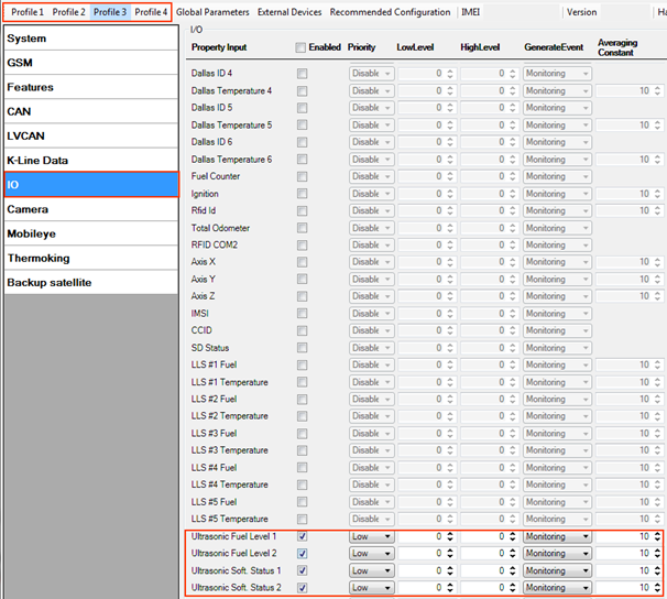
To receive UL202 Fuel Sensor information to the configured server, the Ultrasonic UL202 Fuel level and status have to be enabled in “I/O” section. <br><br> | To receive UL202 Fuel Sensor information to the configured server, the Ultrasonic UL202 Fuel level and status have to be enabled in the “I/O” section. <br><br> | ||
[[image:Ul_io.png]] | [[image:Ul_io.png]] | ||
| Line 114: | Line 100: | ||
[[image:FMB125 UL1.png]] | [[image:FMB125 UL1.png]] | ||
To receive UL202 Fuel Sensor information to the configured server, Ultrasonic UL202-2 Fuel level and status have to be enabled in the “I/O” section. <br> | To receive UL202 Fuel Sensor information to the configured server, the Ultrasonic UL202-2 Fuel level and status have to be enabled in the “I/O” section. <br> | ||
[[image:FMB125_UL2.png]] | [[image:FMB125_UL2.png]] | ||
==FM63XY/FMB630 configuration== | ==FM63XY/FMB630 configuration== | ||
With FM63 00.03.XX version, FM63XY/FMB630 can support Ultrasonic UL202 Fuel sensors. In order to configure device to read UL202 Sensor information, COM1/2 port has to be selected as “UL202-2 Fuel Sensor”. <br> | With FM63 00.03.XX version, FM63XY/FMB630 can support Ultrasonic UL202 Fuel sensors. In order to configure the device to read UL202 Sensor information, the COM1/2 port has to be selected as “UL202-2 Fuel Sensor”. <br> | ||
[[image:FM63_UL1.png]] | [[image:FM63_UL1.png]] | ||
To receive UL202 Fuel Sensor information to the configured server, in preferred device Profile Ultrasonic UL202-2 Fuel level and status have to be enabled in the “I/O” section. <br> | To receive UL202 Fuel Sensor information to the configured server, in preferred device Profile Ultrasonic UL202-2 Fuel level and status have to be enabled in the “I/O” section. <br> | ||
| Line 133: | Line 119: | ||
# The customers need to prepare: 12V power supply, isolating tape, and duster cloth and paper tissue (used to wipe off grease dirt).<br> | # The customers need to prepare: 12V power supply, isolating tape, and duster cloth and paper tissue (used to wipe off grease dirt).<br> | ||
# Before installing on the vehicle, ensure that the vehicle is at the horizontal ground and the fuel tank is placed on frame horizontally.<br> | # Before installing on the vehicle, ensure that the vehicle is at the horizontal ground and the fuel tank is placed on frame horizontally.<br> | ||
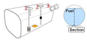
# The installation area of the probe should avoid the fuel filler, fuel outlet, fuel return pipe, fuel float and baffle.<br> | # The installation area of the probe should avoid the fuel filler, fuel outlet, fuel return pipe, fuel float, and baffle.<br> | ||
# Select the flat part at fuel tank bottom or close to the central area as possible.<br> | # Select the flat part at the fuel tank bottom or as close to the central area as possible.<br> | ||
# For circular oil tank, in addition to avoiding the barrier, the tangent plane closest to the ground should be selected.<br> [[image:Ulll.png|300px]] | # For circular oil tank, in addition to avoiding the barrier, the tangent plane closest to the ground should be selected.<br> [[image:Ulll.png|300px]] | ||
# Connect the main body of the sensor with user interface line, extension line, probe connection line.<br> | # Connect the main body of the sensor with user interface line, extension line, probe connection line.<br> | ||
| Line 141: | Line 127: | ||
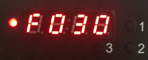
# Hold down “Key 1 for more than 8 seconds and release it to enter input state of total fuel tank height. F030 in the figure below means that the total height of the fuel tank is 30cm. Press “Key 2” to increase and press “Key 3” to decrease. Hold down “key 1” for 8 seconds to confirm the parameters. <br> | # Hold down “Key 1 for more than 8 seconds and release it to enter input state of total fuel tank height. F030 in the figure below means that the total height of the fuel tank is 30cm. Press “Key 2” to increase and press “Key 3” to decrease. Hold down “key 1” for 8 seconds to confirm the parameters. <br> | ||
# After the total height of the fuel tank is put properly, it enters the input state for the current liquid level of the oil tank. E030 in the figure below means that the current liquid level height is 30cm. Press “key 2” to increase and press “key 3” to decrease.<br>[[image:Ell2.png|300px]] | # After the total height of the fuel tank is put properly, it enters the input state for the current liquid level of the oil tank. E030 in the figure below means that the current liquid level height is 30cm. Press “key 2” to increase and press “key 3” to decrease.<br>[[image:Ell2.png|300px]] | ||
# After the current liquid level of the oil tank is put properly, press “key 1” more than 8 seconds to enter the automatic adjustment state of oil tank signal strength. <br> | # After the current liquid level of the oil tank is put properly, press “key 1” for more than 8 seconds to enter the automatic adjustment state of oil tank signal strength. <br> | ||
## At the moment, you may observe whether the displayed height on the display screen is consistent with actual fuel level (for example, the predicted level is about 300mm and displayed 285.2mm).<br> | ## At the moment, you may observe whether the displayed height on the display screen is consistent with the actual fuel level (for example, the predicted level is about 300mm and displayed 285.2mm).<br> | ||
## If the display screen displays 000.0 or the displayed height is quite different from the actual condition, the probe may be moved slightly or grind the fuel tank wall more. In addition, the buzzer in the equipment sounds continuous (if the buzzer sounds on and off or does not sound, it needs to seek the installation point or grind the fuel tank wall more until the buzzer does not sound).<br> | ## If the display screen displays 000.0 or the displayed height is quite different from the actual condition, the probe may be moved slightly or grind the fuel tank wall more. In addition, the buzzer in the equipment sounds continuous (if the buzzer sounds on and off or does not sound, it needs to seek the installation point or grind the fuel tank wall more until the buzzer does not sound).<br> | ||
## Hold down “key 1" for more than 8 seconds to complete search and test of installation point.<br> | ## Hold down “key 1" for more than 8 seconds to complete the search and test of installation point.<br> | ||
[[Category: | [[Category:Accessories]] | ||
Latest revision as of 11:26, 8 October 2021
Main Page > Accessories > UL202 Ultrasonic Fuel SensorIntroduction to the product
UL202 Ultrasonic Fuel Level Sensor connected to FMB640 using the RS232 interface.
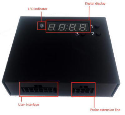
UL202
| Color | Definition of LED light |
|---|---|
| Green light | the probe works normally |
| Red light | the probe is abnormal (the probe line is not inserted or probe drops off) |
Ul202 sensor technical parameters:
| Description | Physical Specification |
|---|---|
| Operating voltage | 9-36VDC |
| Maximum power consumption | 0.8W/12VDC |
| Work temperature | -40°C - +85°C |
| Measurement range | Determined according to materials and thickness of the container |
| Pressure bearing scope | <0.8kg or 0.8MPa |
| Liquid measurement accuracy | +-0.5% |
| Equipment interface | Provided output port of RS232 |
Port definition of user interface - User interface port is used to connect UL202 Ultrasonic Fuel Level Sensor connected to FMB640 using with RS232 interface
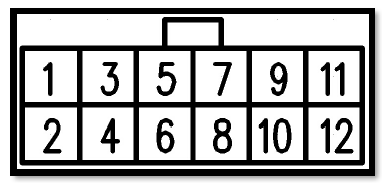
Port definition
| PIN Position Nr. | Function | Description | Color |
|---|---|---|---|
| 1 | Positive pole of Power supply | 9-36VDC | Red |
| 2 | Negative pole of Power supply | - | Black |
| 3 | RS232 TX | RS232 transmitting terminal | Yellow |
| 4 | RS232 RX | RS232 receiving terminal | Red |
| 10 | GND | Ground | Black |
Installation
Before installation, make sure the UL202 Ultrasonic Fuel Level Sensor is not powered ON. The RED and BLACK wires of the User Interface line have to be connected to the Power Supply of the vehicle with the RED wire connecting the positive role and BLACK wire connecting the ground. UL202 has RS232 serial port output:
FMB640, FMC640, FMM640 configuration
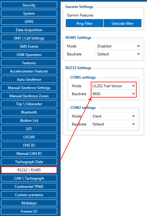
In order to configurate FMB640, FMC640, FMM640 to read UL202 Fuel Sensor information, COM1/2 port have to be selected as “UL202-2 Fuel Sensor”. Baudrate is 9600.
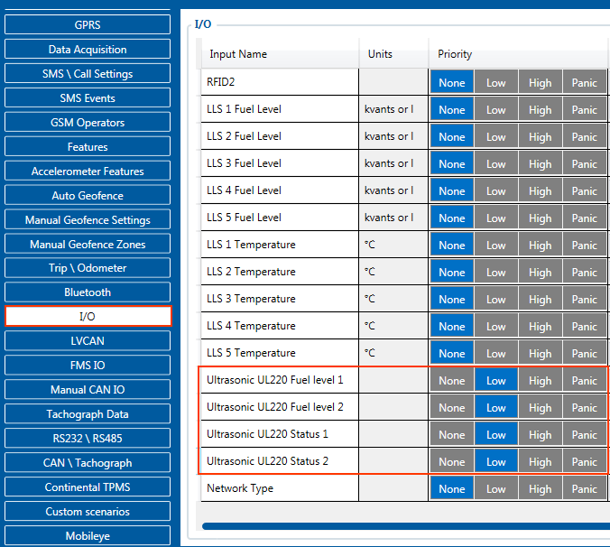
To receive UL202 Fuel Sensor information to the configured server, the Ultrasonic UL202 Fuel level and status have to be enabled in the “I/O” section.
FMB125, FMM125, FMC125, FMU125 configuration
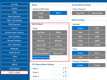
In order to configurate FMB125, FMM125, FMC125, FMU125 to read UL202 Fuel Sensor information, COM1/2 port have to be selected as “UL202-2 Fuel Sensor”. Baud rate is 9600.
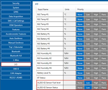
To receive UL202 Fuel Sensor information to the configured server, the Ultrasonic UL202-2 Fuel level and status have to be enabled in the “I/O” section.
FM63XY/FMB630 configuration
With FM63 00.03.XX version, FM63XY/FMB630 can support Ultrasonic UL202 Fuel sensors. In order to configure the device to read UL202 Sensor information, the COM1/2 port has to be selected as “UL202-2 Fuel Sensor”.
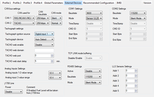 To receive UL202 Fuel Sensor information to the configured server, in preferred device Profile Ultrasonic UL202-2 Fuel level and status have to be enabled in the “I/O” section.
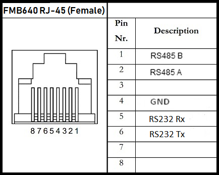
RS232 connection
RS232 Communication: The Yellow wire (TX) is connected with PIN6 RS232 Rx and the Blue wire (RX) is connected with PIN5 RS232 Tx. The Black wire (GND) connected to the Teltonika GNSS device ground.
| NOTE: RS232 is available on both PORT1 and PORT2 |
Installation steps
- Requirements: main body of the sensor, probe, extension line, user interface line, coupling agent, 2.8-meter long hose clamp, sandpaper, and glue.
- The customers need to prepare: 12V power supply, isolating tape, and duster cloth and paper tissue (used to wipe off grease dirt).
- Before installing on the vehicle, ensure that the vehicle is at the horizontal ground and the fuel tank is placed on frame horizontally.
- The installation area of the probe should avoid the fuel filler, fuel outlet, fuel return pipe, fuel float, and baffle.
- Select the flat part at the fuel tank bottom or as close to the central area as possible.
- For circular oil tank, in addition to avoiding the barrier, the tangent plane closest to the ground should be selected.
- Connect the main body of the sensor with user interface line, extension line, probe connection line.
- Power ON control box. The fuel level is displayed 000.0 at the moment.
- Apply coupling agent on the probe surface. Press the probe at the selected installation position. The display of the main body displays the currently measured liquid level.
- Hold down “Key 1 for more than 8 seconds and release it to enter input state of total fuel tank height. F030 in the figure below means that the total height of the fuel tank is 30cm. Press “Key 2” to increase and press “Key 3” to decrease. Hold down “key 1” for 8 seconds to confirm the parameters.
- After the total height of the fuel tank is put properly, it enters the input state for the current liquid level of the oil tank. E030 in the figure below means that the current liquid level height is 30cm. Press “key 2” to increase and press “key 3” to decrease.
- After the current liquid level of the oil tank is put properly, press “key 1” for more than 8 seconds to enter the automatic adjustment state of oil tank signal strength.
- At the moment, you may observe whether the displayed height on the display screen is consistent with the actual fuel level (for example, the predicted level is about 300mm and displayed 285.2mm).
- If the display screen displays 000.0 or the displayed height is quite different from the actual condition, the probe may be moved slightly or grind the fuel tank wall more. In addition, the buzzer in the equipment sounds continuous (if the buzzer sounds on and off or does not sound, it needs to seek the installation point or grind the fuel tank wall more until the buzzer does not sound).
- Hold down “key 1" for more than 8 seconds to complete the search and test of installation point.
- At the moment, you may observe whether the displayed height on the display screen is consistent with the actual fuel level (for example, the predicted level is about 300mm and displayed 285.2mm).
