FMC125 Accelerometer Features settings: Difference between revisions
Kudalevas.da (talk | contribs) Created page with "{{Template:FMB Accelerometer Features settings|model=FMC125|pic_idling=300px|right |dout = Digital output 1 can be activated for a period..." |
No edit summary |
||
| Line 1: | Line 1: | ||
{{Template: | {{Template:FMC Accelerometer Features settings|model=FMC125|pic_idling=[[Image:Fmb125 excessive idling.png|300px|right]] | ||
|dout = Digital output 1 can be activated for a period of time to warn the driver. Output on-time is configured separately for each feature case. For more information please refer to [[DOUT_controls|DOUT controls]]. | |dout = Digital output 1 can be activated for a period of time to warn the driver. Output on-time is configured separately for each feature case. For more information please refer to [[DOUT_controls|DOUT controls]]. | ||
}} | }} | ||
[[Category:FMC125 Configuration]] | [[Category:FMC125 Configuration]] | ||
Revision as of 08:29, 22 August 2019
Main Page > Professional Trackers > FMC125 > FMC125 Configuration > FMC125 Accelerometer Features settingsAccelerometer Calibration
Accelerometer auto calibration functionality has one purpose - determine how FMC device
is mounted in a vehicle. After the calibration process eco driving functionality becomes active
and calibration data will be used to determine harsh acceleration, braking and cornering events.
There are two conditions when auto calibration takes place:
- If on device startup no calibration was detected;
- If the device receives an SMS/GPRS message with auto_calibrate:set text.
After functionality has started FMC device periodically checks current appliance GNSS,
ignition and movement source parameters and if the conditions match:
- position fix got;
- GNSS speed is zero;
- ignition is ON;
- first calibration vector was not saved yet;
Then first vector is taken. Saved vector will be considered as ground vector and it will be
used at further calibration calculations.
Note: When FMC device saves first ground vector vehicle must be parked on flat ground.
Crooked vector may have an impact on further calculations.
Afterwards first ground vector was taken, device analyses conditions:
- position fix got;
- GNSS speed is at least 20 km/h;
- ignition is ON;
- second vector was not saved yet;
- vehicle driving in the same direction with 5⁰ tolerance;
- vehicle speed increase by 7km/h within 1 second.
For next vector. Second vector will be taken if all conditions match. Immediately after
second vector is received, it will be multiplied by first (ground) vector, the result of these
vectors is vector multiplication cross product which is the right side of a car. By using
same vector multiplication method, device front, left side will be calculated. At this point
calibration is successfully ended as indication device sends an SMS/GPRS message with
Device is calibrated, to recalibrate send:auto_calibrate:set.
Note: SMS/GPRS message will be sent only if auto calibration functionality was triggered by
SMS/GPRS message.
For user convenience in case auto calibration functionality fails then notification message
will be sent. For exact messages, check algorithm section.
Note: SMS/GPRS message will be sent only if auto calibration functionality was triggered by
SMS/GPRS message.
To get current calibration status auto_calibrate:get SMS/GPRS command must be sent to
the device. If device is calibrated it will respond with Calibration state: calibrated or otherwise
Calibration state: not calibrated. Also this command returns saved Ground and Side vectors.
After every TRIP START event, device starts shadow calibration. This type of calibration is
running in parallel with already saved vectors (this means that vectors does not reset until
shadow calibration have both new vectors). After shadow calibration is done, device updates the
vector values to the new ones. There are two conditions when shadow calibration does not run
at TRIP start event:
- Normal calibration is still running.
- Shadow calibration is still running from previous TRIP event.
To take ground vector these conditions should be met:
- Ignition is ON
- Device got GPS FIX
- Vehicle speed = 0km/h
Device will check these conditions every 1sec until they will pass.
To take side vector these conditions should be met:
- Vehicle speed >= 20km/h
- Device got GPS FIX
- Ignition is ON
- Device angle does not change more than 5 degrees in past 1 sec
- Speed need to increase by 7km/h in 1s period.
Device will check these conditions every 1 sec until they will pass.
Excessive Idling
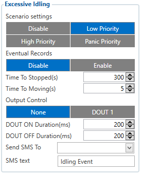
When vehicle stops for a specific amount of time the scenario is activated, a record will be generated and digital output status will be changed to 1 when configured. You can configure the time it takes to turn on this scenario (Time to Stopped). Scenario is activated until the vehicle starts moving (movement is detected only by the accelerometer) and keeps moving for an amount of time that is configured. You can configure the time it takes to turn off this scenario (Time to Moving)
Digital output 1 can be activated for a period of time to warn the driver. Output on-time is configured separately for each feature case. For more information please refer to DOUT controls.
Unplug Detection
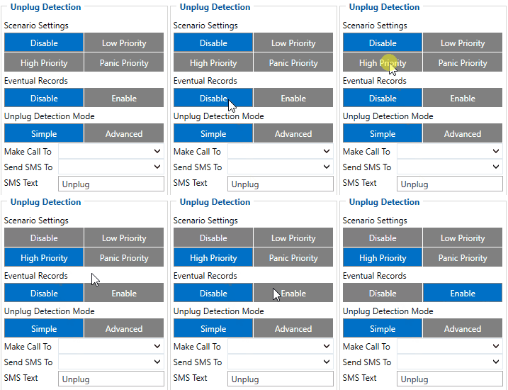
An event will be generated when FMC125 is unplugged from external power or plugged back in again.
Scenario settings
- Disable - disable scenario.
- Low Priority - when low priority event is triggered, device makes additional record with indication of event cause.
- High Priority - module makes additional record with High priority flag and sends event packet immediately to the server by
GPRS.
- Panic Priority - triggers same actions as High priority, but if GPRS fails, it sends AVL packet using SMS mode if SMS is enabled in SMS Data Sending settings.
Eventual Records
- Disable - scenario status value is sent in each AVL record.
- Enable - scenario status value is sent only in eventual AVL records.
Unplug Detection mode
- Simple - unplug detection according to external voltage only. Is used in cars where power voltage is not dependent on ignition (recommended).
- Advanced - unplug detection according to external votage and accelerometer. Is used in cars where power voltage is disconnected when ignition is switched off.
Towing Detection
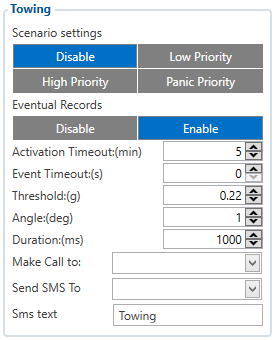
Towing Detection feature helps to inform the driver about unexpected car movement when it was parked. FMC125 generates an event when car is being towed or lifted, for example, in a case of vehicle evacuation. FMC125 activates towing function when following conditions are met:
- Ignition (configured Ignition Source) is OFF.
- Activation Timeout is reached.
When towing function is engaged FMC125 monitors accelerometer data. If acceleration Threshold or Angle reach configured values for a configured Duration, and Ignition is still OFF for a period of time that is longer than Event Timeout, then an event is generated. When configured, Make Call To and Send SMS To functions make a call or send an SMS to a predefined phone number. Towing function will be reactivated after FMC125 detects a change of Ignition state from ON to OFF.
Crash Detection
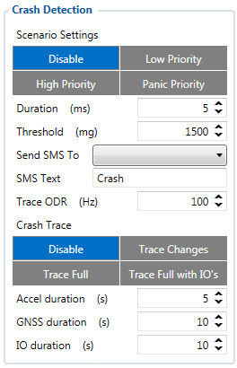
If Crash Detection is enabled, it monitors acceleration on each axis which helps to detect an accident. Threshold and Duration values are set depending on the impact magnitude that is required to be detected. FMC125 can detect events ranging between a slight tapping on the device and a severe accident.
If Crash Trace is disabled only one eventual crash record will be generated when Duration (ms) and Threshold (mg) values are exceeded.
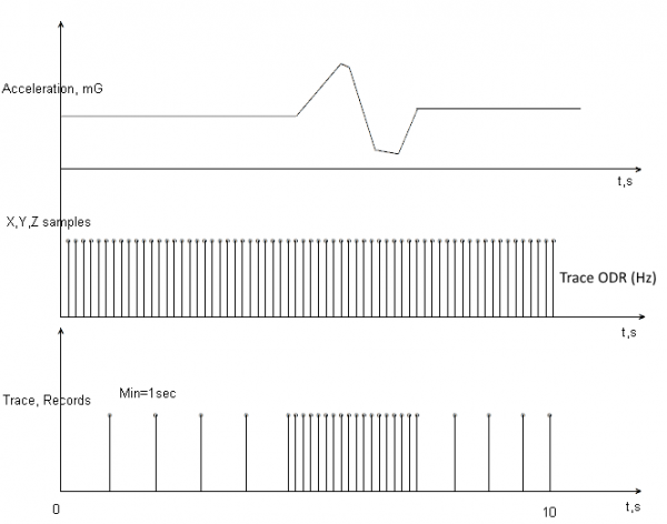
If Crash Trace is enabled, FMC125 will collect crash trace data with frequency defined by Trace ODR (Hz) parameter. Acceleration, GNSS and IO data monitoring duration during the crash event is defined by these parameters:
- Accel duration (s). Acceleration data duration can be set for up to 15 seconds before crash event and 15 seconds after;
- GNSS duration (s). GNSS data duration can be set for up to 30 seconds before crash event and 30 seconds after.
- IO duration (s). IO data duration can be set for up to 30 seconds before crash event and 30 seconds after.
There are three configurable Crash Trace modes:
Trace Full
- Data tracked: all GNSS and acceleration data
Trace Full with IO's
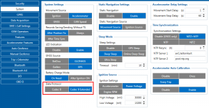
- Data tracked: all GNSS and acceleration data with IO's, configured in I/O settings as "Crash" parameter (see picture below)

Trace Changes
- Data tracked: GNSS and acceleration data, when acceleration values are changed by more then 50mG
NOTE: with Crash Trace mode enabled, it is recommended to use Codec 8 Extended Data Protocol. This helps to optimize crash trace data sending from device to server.
Each record will have accurate timestamps in milliseconds.
Crash Data Visualisation
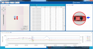
With Teltonika CrashDataVisualizer tool you can analyze crash trace data visually: determine impact to vehicle direction, view crash trace on the map, also see the change of mG and speed values during crash time period. CrashDataVisualizer is dedicated to work with TAVL application, it means that only crash trace log files exported from TAVL is compatible. To have ability to export crash trace log files, device must be configured to send data by Codec8E.
To start using CrashDataVisualizer
Download and install TAVL (version 4.15.0.1 or later) + CrashDataVisualizer applications from here:
Link: https://drive.teltonika.lt/d/05369fc90d9744afb14f/
Password: TJEk24YApbRhWrQQ
To get crash data
Login to TAVL application (please contact your Sales manager for TAVL login information).
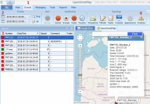
In TAVL application:
1. Go to Events
2. Set the date of event
3. Select the object you want to analyze
4. Press "Crashes" button
Crash event list window will show up. Press Download icon and save crash event file (.JSON).
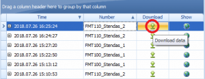
Viewing crash data in application
Open CrashDataVisualizer application. Drag and Drop or Browse crash data file (.JSON).
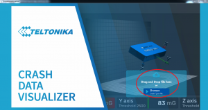
Use the Visualizer.
