Teltonika DualCam: Difference between revisions
| Line 175: | Line 175: | ||
| rowspan="1" colspan ="1" style="text-align: center; style="width: 150px; background: white; color: black;" | 30 | | rowspan="1" colspan ="1" style="text-align: center; style="width: 150px; background: white; color: black;" | 30 | ||
|} | |} | ||
<br> | |||
==Camera Scenario Settings== | ==Camera Scenario Settings== | ||
[[Image:CameraScenarioSettings.PNG|{{{general|size}}}|right]] | [[Image:CameraScenarioSettings.PNG|{{{general|size}}}|right]] | ||
Revision as of 08:08, 2 December 2020
Main Page > Video Solutions > Teltonika DualCamIntroduction to the product
Teltonika DualCam is connected to FMX125 and FMU126 devices using the RS232 interface.
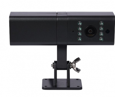
Basic characteristics
| Technical data | Description |
|---|---|
| Supported by | FMC125, FMM125, FMU125, FMU126, FMB125 |
| Day & Night Vision Effect | Day (Color), Night (Black & White) |
| Angle of View | Horizontal 120°, Vertical 70° |
| Dual Camera | Front and Rear (equal characteristics) |
| Camera casing dimensions | 126.2 x 36.6 x 36.6 mm |
| Camera mounting | Sticky tape (3M) or screws |
| Electrical parameters | Description |
|---|---|
| Input voltage range | 9-36 V |
| Working temperature and humidity | 30C~85C Humidity<90% |
| Stand-by electric current | 60 mA |
| Function parameters | Description |
|---|---|
| Real time clock (RTC) synchronization | Available over FM (via NTP, NITZ or GNSS) |
| Picture resolution | 1280 x 720 (default) (50KB transfer period 18 sec), Configurable: 160 x 120; 320 x 240; 640 x 480; 1920 x 1080 |
| IR Distance | 2 Meters |
| Cable length | RS232 (0.35 m) |
| Video compression | H.265 |
| Video resolution | 720P (20 sec. – 6MB, transfer period ~320sec.) |
| Video storage | 2psc. MicroSD card (Max 64G up to 72 hours of video) |
Installation
To connect the DualCam to a supported device, you have to make sure to connect 4 PINs of the camera to the PINs of your device correctly.
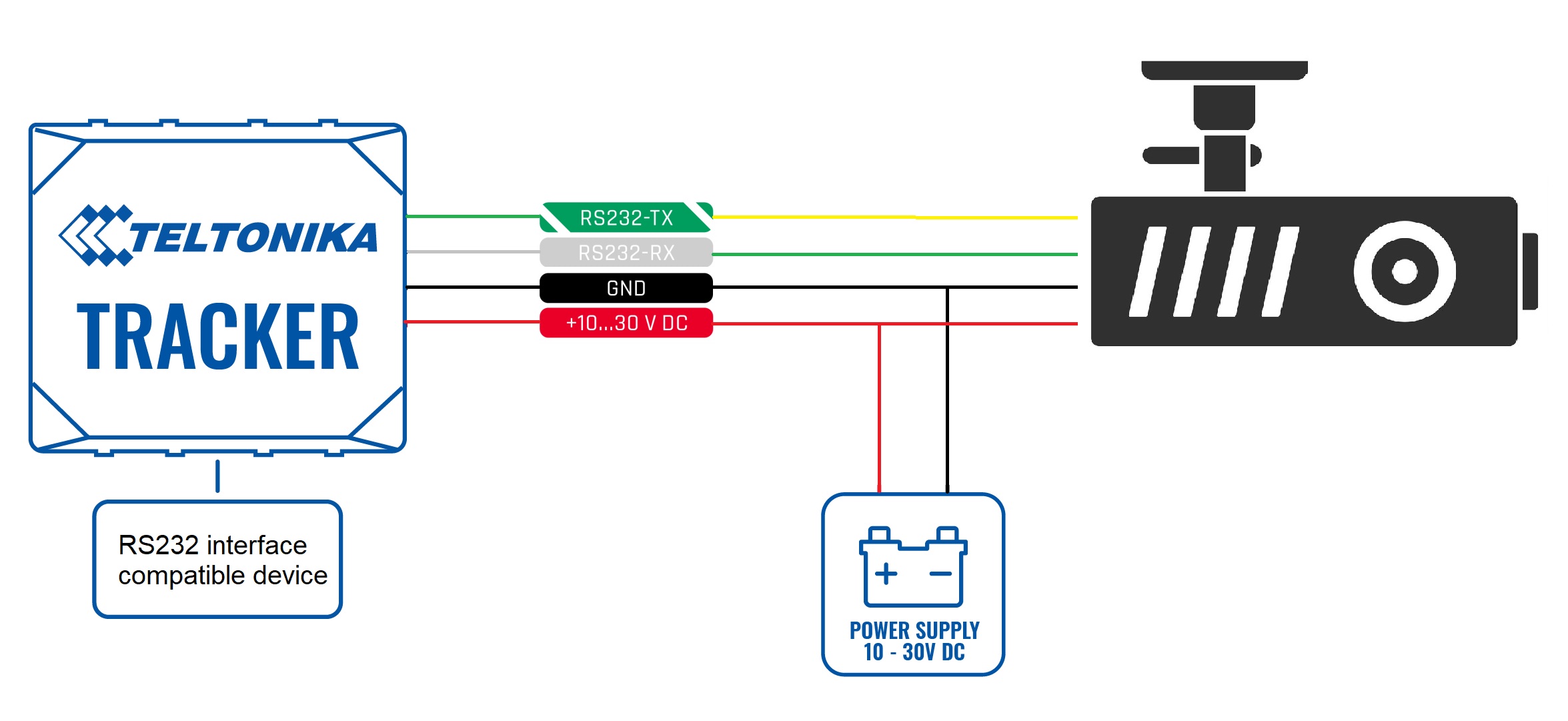
| PIN NUMBER | PIN NAME |
DESCRIPTION |
|---|---|---|
| 1 | RS232-Tx | DualCam output for data transmission through RS232 |
| 2 | RS232-Rx | DualCam input for data reception through RS232 |
| 3 | VCC(9-36V) (+) | Power supply for the DualCam |
| 4 | GND (-) | Ground |
DualCam RS232 camera support
DualCam camera support was introduced from firmware version 03.27.00.Rev.86. A new RS232 mode "DualCam" was added with parameters for setting control. The details of the RS232 mode parameter are provided in the table below.
| Parameter name | Parameter ID | Parameter value |
|---|---|---|
| RS323 Mode | 151 | 18 |
Camera Feature Settings
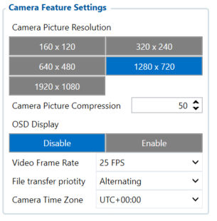
Once this mode is enabled, new tab “Camera Settings” appears on the left sidebar. This will contain the main parameters for configuring the camera settings The parameter IDs and values are provided in the table below. Once configuration is
saved to device, these parameters are updated.
| Parameter name | Parameter ID | Parameter values | Default values |
|---|---|---|---|
| Camera Picture Resolution | 66000 | ||
| 0 - 160 x 120 | 3 | ||
| 1 - 320 x 240 | |||
| 2 - 640 x 480 | |||
| 3 - 1280 x 720 | |||
| 4 - 1920 x 1080 | |||
| Camera Picture Compression | 66001 | [0 - 100] (%) | 50 |
| OSD Display | 66002 | 0 - Disabled | 0 |
| 1 - Enabled | |||
| Video Frame Rate | 66003 | [1-30] (frames per second) | 30 |
Camera Scenario Settings
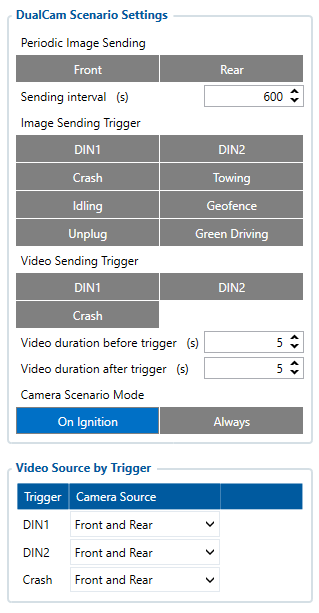
„Camera settings" tab also contains scenario settings that trigger camera video/photo capture when specific condition is met.
| Parameter name | Parameter ID | Parameter values | Default values |
|---|---|---|---|
| Periodic Image sending | 66006 | 0 - Disabled | 0 |
| 1 - Enabled | |||
| Sending interval | 66007 | [10-1800] (seconds) | 600 |
| Video sending trigger | 66008 | ||
| 0 - None | 0 | ||
| 1 - DIN1 | |||
| 2 - DIN2 | |||
| 3 - Crash | |||
| Video duration before trigger | 66009 | [1-10] (seconds) | 5 |
| Video duration after trigger | 66010 | [1-10] (seconds) | 5 |
Periodic image sending scenario
Periodic image sending triggers photo capture from a front camera, whenever the timeout is reached (sending interval parameter). If a camera has not finished uploading picture to a server, then the photo capture is skipped.
Video sending by trigger
Video sending by trigger scenario monitors the selected trigger (video sending trigger parameter) and captures video before and after the event (video duration before trigger and video duration after trigger parameters). If the previously captured video has not finished downloading, then a new video capture is skipped until the old one has been sent. When this scenario is triggered, high priority eventual record is generated with the value corresponding to what triggered the scenario. See the table below.
| Parameter name | Parameter ID | Parameter value |
|---|---|---|
| SOS trigger | 499 | 0 - Server request |
| 1 - DIN1 | ||
| 2 - DIN2 | ||
| 3 - Crash |
Camera request command
A new camera request has been added, which allows server to request files from a camera. The format is as provided below in the table:
| Command | Arguments | Explanation |
|---|---|---|
| camreq: | <file_type>,<file_source>,<timestamp>,<duration> | Captures appropriate file with the provided details. If the connection to server is opened, them files immediately become available for download. If not, then connection is tired to be made. |
The arguments are as follows:
- <file_type>
- 0 - Video
- 1 - Photo
- <file_source>
- 1 - Front camera
- 2 - Rear camera
- 3 - Both cameras
- <timestamp>
- Unix timestamps in decimal (not required for photo download)
- <duration>
- Video duration in seconds from provided timestamps (not required for photo download), (up to 255 s)
| Conditions | Command response |
|---|---|
| Arguments are invalid | Invalid argument in camera request cmd! |
| Photo requested | Request for photo from source <1-3> received |
| Video requested | Request for video from source <1-3> received for <1-255> seconds since YYYY-MM-DDHH:MM:SS |
Camera ping transmission and TF status checking
Camera pinging was implemented to periodically check if a camera is connected to a device. This is done via “Get TF status” command for both front and rear camera every 20 seconds when ignition is on. The received result from this command is stored in two corresponding AVL elements “Front camera state” and “Rear camera state”. The following do not only store TF status, but also if response from the camera was received or not.
| Parameter name | Parameter AVL ID | Parameter values |
|---|---|---|
| Front camera state: | 498 | 0 - Camera not detected |
| 1 - No card | ||
| Rear camera state: | 497 | |
| 2 - Card mount failed | ||
| 3 - Card failed | ||
| 4 - Card faulty |
Camera RTC synchronization
Camera RTC synchronization is done anytime the device itself is synchronized (via NTP, NITZ or GNSS).
Camera is configured if all of these conditions are met:
- RS232 mode is selected (DualCam)
- Camera was not configured since startup or one of the related parameters were changed (compression, framerate or OSD)
- Camera file transfer is not active
Active camera reconfiguration is accompanied by two consecutive camera shutter clicks. If camera is disconnected and later reconnected, a device will detect it by periodic camera ping packet. Once camera is detected, the device will reissue the reconfiguration procedure.
Camera file transfer reconnection
If FMU1YX device has bad reception, server is not reachable or wrong server details are configured, then the device tries to open a link to a camera server few consecutive times. If no connection was possible to be established, then the connection is postponed for 30 minutes and tried again (or tried every configured sending interval if periodic image sending is enabled).
DualCam camera file transfer support
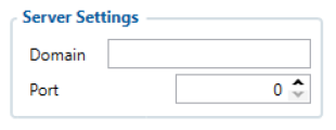
Once camera has at least one file captured, it starts connection to a remote server, which is configured by parameters “Domain” and “Port” found in the “Camera Settings” tab.
Initialization packet
On connection, a device sends an initialization packet.
| Header(0x0000) | Protocol ID | IMEI | Settings |
|---|---|---|---|
| 2 bytes | 2 bytes | 8 bytes | 4 bytes |
Protocol ID – just a reference for the protocol version that is running on a device (for server cross compatibility with older versions). Firmware FMB.Ver.03.27.00.Rev.86 and up have protocol ID 5. Settings flag contains information on what is available for download. Structure is provided below:
| Settings, 4 B | |||||||||||||||||||||||||||||||
|---|---|---|---|---|---|---|---|---|---|---|---|---|---|---|---|---|---|---|---|---|---|---|---|---|---|---|---|---|---|---|---|
| Byte 3 | Byte 2 | Byte 1 | Byte 0 | ||||||||||||||||||||||||||||
| 1 | 2 | 3 | 4 | ||||||||||||||||||||||||||||
- Video, rear (%videor)
- Video, front(%videof)
- Photo, rear (%photor)
- Photo, rear (%photor)
If identifier sent to a server is not valid, device disconnects.
General command structure
General communication packet structure is as in the table bellow. It consist of CMD_ID (2 bytes), Data length of a command and a payload.
| Command ID | Data length | Data |
|---|---|---|
| 2 bytes | 2 bytes | [data length] bytes |
Close a session command (CMD ID 0x0000)
In case when a device connects to a server, but the server does not expect it to connect, server will respond by sending a CLOSE command after which the connection will be terminated. This command is also used when device connects to a server for a custom file sending and server finishes to send all custom files to the device.
| Command ID | Data length |
|---|---|
| 0x0000 | 0x0000 |
Start file transfer command (CMD ID 0x0001)
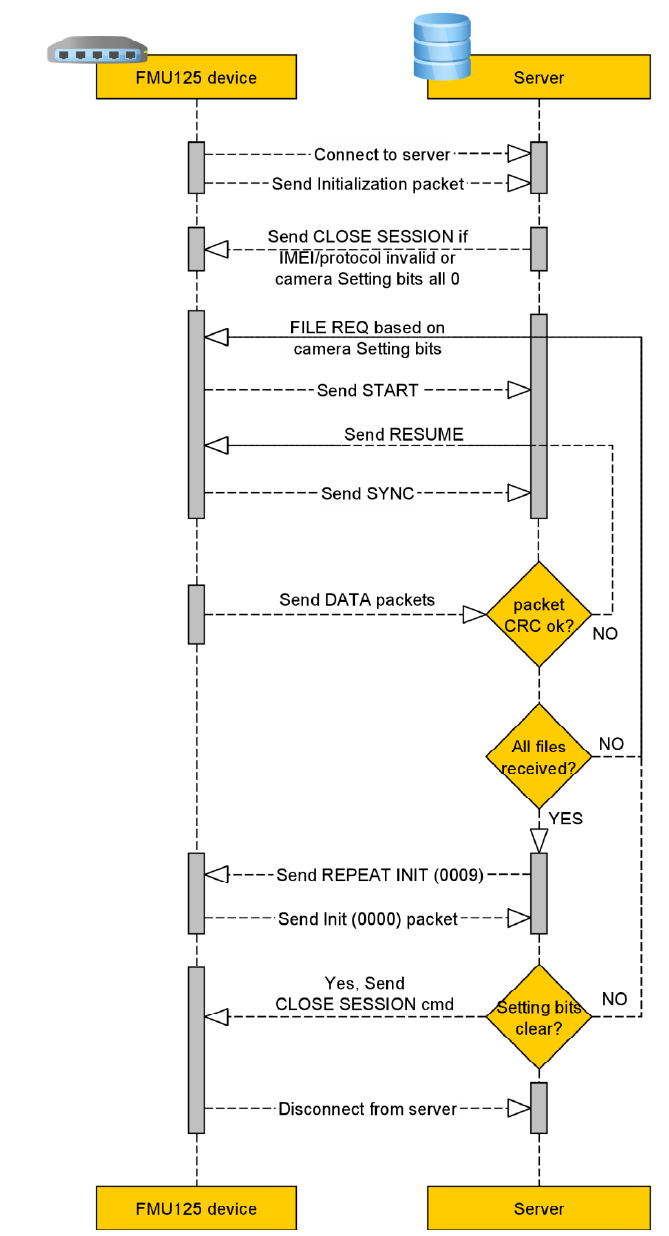
After device is connected for a file download, server initiates file transfer by sending a START command.
| Command ID | Data length | File Packets (4 bytes) | File CRC (2 bytes) |
|---|---|---|---|
| 0x0004 | 0x0006 | 0x12345678 | ... |
File request command (CMD ID 0x0008)
After device is connected for a file upload, server initiates file transfer by sending a FILE REQ command.
| Command ID | Data length | File Identifier |
|---|---|---|
| 0x0008 | 2 bytes | See the table below |
Device should answer with a START command described above indicating a size and crc of the requested file.
| File source, type | Identifier (ASCII chars) |
|---|---|
| Photo from camera, rear | %photor |
| Photo from camera, front | %photof |
| Video from camera, rear | %videor |
| Video from camera, front | %videof |
Resume file transfer command (CMD ID 0x0002)
In a response to the START command a RESUME command must be sent from a server.
| Command ID | Data length | Packet offset (4 bytes) |
|---|---|---|
| 0x0002 | 0x0004 | 0x00000000 |
To begin a file transfer from the start, offset should be set to zero (4 bytes value). In case when the file transfer has been interrupted, to resume file transfer, offset can be set to the desired value (0 ≤ [offset] ≤ [file size]).
Synchronize file transfer command (CMD ID 0x0003)
In a response to the RESUME command a SYNC command is sent from device.
| Command ID | Data length | File offset (4 bytes) |
|---|---|---|
| 0x0003 | 0x0004 | 0x00000000 |
By sending a SYNC command, it is ensured that the next data command will contain a file data starting from the specified offset.
File data transfer command (CMD ID 0x0004)
After sending a SYNC command, a file data transfer is started by sending DATA commands.
| Command ID | Data length | File data (up to 1024 bytes) | Data CRC (2 bytes) |
|---|---|---|---|
| 0x0004 | 0x0402 | ... | ... |
A File data is split into 1024 byte parts, each part wrapped into a DATA command and is sent.
Note: if a command with a bad CRC is received, RESUME command should be sent with the last valid file offset, after receiving a RESUME command, server will stop sending DATA commands and continue communication from “Error! Reference source not found.” step.
CRC polynomial expression: 0x8408
Initial value, when calculating CRC, is previously received packet (CMD ID 0x0004) CRC value.
File transfer status command (CMD ID 0x0005)
After a file transfer is completed and no more files are required from the device, a server should send a COMPLETED command to the device (this command does not work after executing repeat init command0 x0009 – in this case the server should send a CLOSE session 0x0000 command mentioned before).
| Command ID | Data length | Status (4 bytes) |
|---|---|---|
| 0x0005 | 0x0004 | 0x00000000 |
In case of the server using invalid arguments, commands or not following the file request flow, the device will send this command with a Status field set to one of the few possible error codes. List of possible ones is provided below.
| Status value (hexadecimal) | Description | Notes |
|---|---|---|
| 0x00000000 | File transfer process completed | Sent from server |
| 0x00000002 | Failed to close GPRS | Sent from device |
| 0x00000003 | Failed to close socket | Sent from device |
| 0x00000005 | Invalid response from server to init packet | Sent from device |
| 0x00000011 | This error code forces the device to disconnect from server | Sent from device. Possible causes:
|
After a COMPLETED command device should disconnect from the server. ==Initialization packet repeat command (CMD ID 0x0009) When sent, the initialization packet is repeated. This is used, when all of the files are downloaded and additional check is carried out for any additional files, that may have been captured during the download operation.
File transfer visual flow
