Template:FTX First Start: Difference between revisions
Tag: Manual revert |
|||
| Line 353: | Line 353: | ||
| FTC880 | | FTC880 | ||
| FTC305 | | FTC305 | ||
| FTM305 = | | FTM305 = | ||
| Line 373: | Line 372: | ||
* Check if power is still available when you turn off any of vehicles devices. | * Check if power is still available when you turn off any of vehicles devices. | ||
* Ignition is connected to the ignition relay output. As alternative, any other relay, which has power output when ignition is on, may be chosen. | * Ignition is connected to the ignition relay output. As alternative, any other relay, which has power output when ignition is on, may be chosen. | ||
'''CONNECTING GROUND WIRE''' | |||
* Ground wire must be connected to the vehicle frame or metal parts that are fixed to the frame. | |||
* If the wire is fixed with the bolt, the loop must be connected to the end of the wire. | |||
* For better contact scrub paint from the spot where loop is going to be connected. | |||
| FTM880 = | |||
'''CONNECTING WIRES''' | |||
* Wires should be fastened to the other wires or nonmoving parts. Do not place the wires near moving or heat-emitting objects. | |||
* All electrical connections must be properly isolated. No bare wires should be visible. Re-apply isolation to wires if you removed factory isolation during installation. | |||
* If the wires are placed in the exterior or in places where they can be damaged or exposed to heat, humidity, dirt, etc., additional isolation should be applied. | |||
'''CONNECTING POWER SOURCE''' | |||
* Ensure that after the vehicle computer falls asleep, power is still available on chosen wire. Depending on vehicle, this may happen in 5 to 30 minutes period. | |||
* When module is connected, measure voltage again to make sure it did not decrease. | |||
* It is recommended to connect main power cable to the main battery of the vehicle. | |||
'''CONNECTING GROUND WIRE''' | '''CONNECTING GROUND WIRE''' | ||
Revision as of 16:35, 3 April 2025
[[Image:{{{model}}} side.png|thumb|400x300px|right|upright=0.35|{{{model}}}]]
KNOW YOUR DEVICE
[[Image:{{{model}}} know your device.png|400px]]
SET UP YOUR DEVICE
 |
Physical SIM card insertion/removal must be performed when device is powered off – external voltage disconnected. Otherwise, the SIM card might be damaged or device will not detect it. |
[[Image:{{{model}}} setup.png|1000px|left]]
PINOUT
PC CONNECTION (WINDOWS)
HOW TO INSTALL USB DRIVERS (WINDOWS)
- Please download COM port drivers from here.
- Extract and run TeltonikaCOMDriver.exe.
- Click Next in driver installation window.
- In the following window click Install button.
- Setup will continue installing the driver and eventually the confirmation window will appear. Click Finish to complete the setup.
CONFIGURATION (WINDOWS)
Most Teltonika devices are shipped with default factory settings. Use Telematics Configuration Tool (TCT) to change these settings according to your needs.
| PIN NUMBER | PIN NAME | DESCRIPTION |
[[Image:{{{model}}}_pinout.png|400px|center]]
|
|---|
| Configurator | TCT | |
|---|---|---|
| Operating system | Windows 7 Windows 8.1 Windows 10 Windows 11 |
Windows 10 Windows 11 |
| MS .NET Framework version | MS .NET framework 5.0 | MS .NET framework 6.0 |
| Version | 64 bit | 64 bit |
| Disk Storage | 1 GB of free disk space | |
| Internet | Ethernet port or Wi-Fi w/ network access for auto-update |
TCT
- Download the TCT (compressed archive).
- Extract the archive and launch the executable. The TCT will be installed.
- Launch the TCT.
- In the Discovered devices list, select your device and press Configure.
- The Device status window opens. It contains device, GNSS and Cellular information.
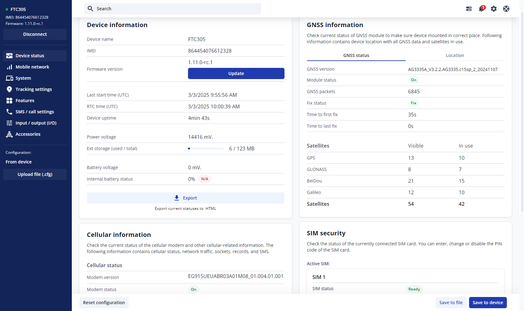
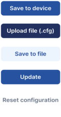


Save to device – saves configuration to device.
Upload file – loads configuration from file.
Save to file – saves configuration to file.
Update – update device firmware.
Reset configuration – sets device configuration to default.
Most important configuration sections are Mobile network (Server, Mobile network settings) and Tracking settings (data collection parameters). More details about {{{model}}} configuration using TCT can be found here.
QUICK SMS CONFIGURATION
The default configuration ensures best track quality and optimal data usage.
Quickly set up your device by sending this SMS command to it:

DEFAULT CONFIGURATION SETTINGS

After successful SMS configuration, {{{model}}} device will synchronize time and update records to configured server. Time intervals and default I/O elements can be changed by using TCT or Parameter list.
MOUNTING RECOMMENDATIONS
LED INDICATIONS
This section is an explanation of LED indications on {{{model}}} device.
BASIC CHARACTERISTICS
[[Category:{{{model}}}]]