Line 1:
Line 1: {{Template:FMB1 First start card|model=FMB202|antenna=internal GNSS/GSM antennas|pic=[[Image:FMB202 man.png|600px|right]]}}
{{Template:FMB2_First_start_card |model=FMB202|antenna=internal GNSS/GSM antennas|pic=[[Image:FMB202 man.png|600px|right]]}}
<font size="+3"><span style=color:#104996>'''2x6 socket pinout'''</span></font>
{| class="wikitable"
|+
! style="background: white; color: #F6A83E;" | Pin number
| style="background: white; color: #F6A83E;" | Pin name
| style="background: white; color: #F6A83E;" | Description
| style="background: white; color: #F6A83E;" rowspan="13" | [[Image:Fmb_120_2x6_pinout.png|200px|center]]
|-
| style="text-align: left; background: #F6F6FB;" | 1
| style="text-align: left; background: #F6F6FB;" | <span style=color:#FF0000>'''VCC'''</span> (10-30)V DC (+)
| style="text-align: left; background: #F6F6FB;" | Power supply (+10-30 V DC).
|-
| style="text-align: left; background: #F6F6FB;" | 2
| style="text-align: left; background: #000000;" | <span style=color:#808080>'''AIN 1'''</span>
| style="text-align: left; background: #F6F6FB;" | Analog input, channel 1. Input range: 0-30 V DC.
|-
| style="text-align: left; background: #F6F6FB;" | 3
| style="text-align: left; background: #000000;" | <span style=color:#FFFFFF>'''AIN 2 / DIN 3'''</span>
| style="text-align: left; background: #F6F6FB;" | Analog input, channel 2. Input range: 0-30 V DC / Digital input, channel 3.
|-
| style="text-align: left; background: #F6F6FB;" | 4
| style="text-align: left; background: #000000;" | '''<span style=color:#00FF00>D</span><span style=color:#FFFFFF>IN</span><span style=color:#00FF00> 2</span>'''
| style="text-align: left; background: #F6F6FB;" | Digital input, channel 2.
|-
| style="text-align: left; background: #F6F6FB;" | 5
| style="text-align: left; background: #000000;" | <span style=color:#FFFF00>'''DIN 1'''</span>
| style="text-align: left; background: #F6F6FB;" | Digital input, channel 1.
|-
| style="text-align: left; background: #F6F6FB;" | 6
| style="text-align: left; background: #000000;" | '''<span style=color:#0000FF>IN</span><span style=color:#FFFFFF>PU</span><span style=color:#0000FF>T 6</span>'''
| style="text-align: left; background: #F6F6FB;" | TX EXT (LVCAN – TX).
|-
| style="text-align: left; background: #F6F6FB;" | 7
| style="text-align: left; background: #F6F6FB;" | <span style=color:#000000>'''GND''' </span>(-)
| style="text-align: left; background: #F6F6FB;" | Ground.
|-
| style="text-align: left; background: #F6F6FB;" | 8
| style="text-align: left; background: #000000;" | '''<span style=color:#FFA500>D</span><span style=color:#FFFFFF>OU</span><span style=color:#FFA500>T 1</span>'''
| style="text-align: left; background: #F6F6FB;" | Digital output, channel 1. Open collector output. Max. 3,3 A DC.
|-FFA500
| style="text-align: left; background: #F6F6FB;" | 9
| style="text-align: left; background: #000000;" | <span style=color:#800080>'''DOUT 2'''</span>
| style="text-align: left; background: #F6F6FB;" | Digital output, channel 2. Open collector output. Max. 3,3 A DC.
|-
| style="text-align: left; background: #F6F6FB;" | 10
| style="text-align: left; background: #000000;" | <span style=color:#0000FF>'''1WIRE POWER'''</span>
| style="text-align: left; background: #F6F6FB;" | +3,8 V output for 1–Wire devices.
|-
| style="text-align: left; background: #F6F6FB;" | 11
| style="text-align: left; background: #000000;" | <span style=color:#00FF00>'''1WIRE DATA'''</span>
| style="text-align: left; background: #F6F6FB;" | Data for 1–Wire devices.
|-
| style="text-align: left; background: #F6F6FB;" | 12
| style="text-align: left; background: #000000;" | '''<span style=color:#FFFF00>IN</span><span style=color:#FFFFFF>PU</span><span style=color:#FFFF00>T 5</span>'''
| style="text-align: left; background: #F6F6FB;" | RX EXT (LVCAN - RX).
|-
|}
{{Template:FMB First start config|model=FMB202|config_link=[[FMB202 Configuration|here]]}}
{{Template:FMB1 Mounting recommendations|model=FMB202}}
https://teltonika.lt/product/FMB202-internal-gnss-antenna-battery/
FMB202 Small and professional waterproof tracker with high gain internal internal GNSS/GSM antennas, Bluetooth and high capacity internal Ni-MH battery
File:FMB202 man.png
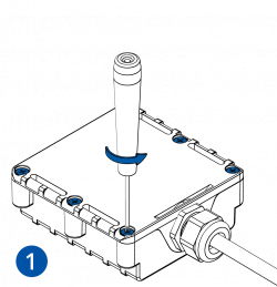
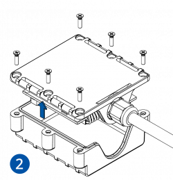
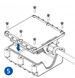
How to insert Micro-SIM card Unscrew 6 screws counter-clockwise that are located on the bottom of the device.Remove the cover .
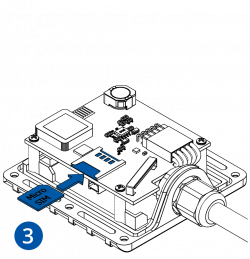
Insert Micro-SIM card as shown with PIN request disabled or read Security info Configurator . Make sure that Micro-SIM card cut-off corner is pointing forward to slot.
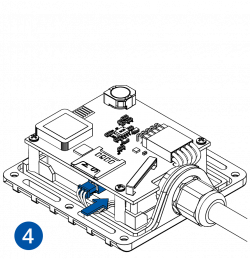
Connect battery as shown to device.
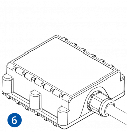
After configuration, attach device cover and put the screws back in.
Device is ready to be connected.
Micro-SIM card insertion/removal must be performed when device is powered off – external voltage and battery are disconnected. Otherwise Micro-SIM card might be damaged or device will not detect it.
Cable colors
PIN NUMBER
PIN NAME
DESCRIPTION
Red VCC (6-30)V DC (+)
Power supply (+6...30 V DC).
Black GND (-)
Ground.
Yellow DIN 1
Digital input, channel 1.
White/Green DIN 2
Digital input, channel 2.
White DIN 3
Digital input, channel 3.
Grey AIN 1
Analog input, channel 1. Input range: 0-30 V DC.
White/Orange DOUT 1
Digital output, channel 1. Open collector output. Max. 3,3 A DC.
Violet DOUT 2
Digital output, channel 2. Open collector output. Max. 3,3 A DC.
Green 1WIRE DATA
Data channel for 1–Wire devices.
Blue 1WIRE POWER
+3,8 V output for 1–Wire devices.


