FMB964 First Start: Difference between revisions
Appearance
No edit summary |
No edit summary |
||
| Line 2: | Line 2: | ||
<font size="+3"><span style=color:#104996>'''FMB964 device pinout'''</span></font> | <font size="+3"><span style=color:#104996>'''FMB964 device pinout'''</span></font> | ||
{| class="wikitable" | |||
|+ | |||
! style="background: white; color: #F6A83E;" | Pin number | |||
| style="background: white; color: #F6A83E;" | Pin name | |||
| style="background: white; color: #F6A83E;" | Description | |||
|- | |||
| style="text-align: left; background: #F6F6FB;" | 1 | |||
| style="text-align: left; background: #F6F6FB;" | <span style=color:#FF0000>'''VCC'''</span> (10-30)V DC (+) | |||
| style="text-align: left; background: #F6F6FB;" | Power supply (+10-30 V DC). | |||
|- | |||
| style="text-align: left; background: #F6F6FB;" | 2 | |||
| style="text-align: left; background: #F6F6FB;" | <span style=color:#000000>'''GND''' </span>(-) | |||
| style="text-align: left; background: #F6F6FB;" | Ground. | |||
|- | |||
| style="text-align: left; background: #F6F6FB;" | 3 | |||
| style="text-align: left; background: #000000;" | <span style=color:#FFFF00>'''DIN 1'''</span> | |||
| style="text-align: left; background: #F6F6FB;" | Digital input, channel 1. DEDICATED FOR IGNITION INPUT | |||
|- | |||
| style="text-align: left; background: #F6F6FB;" | 4 | |||
| style="text-align: left; background: #000000;" | <span style=color:#808080>'''AIN 1'''</span> | |||
| style="text-align: left; background: #F6F6FB;" | Analog input, channel 1. Input range: 0-30 V DC. | |||
|- | |||
| style="text-align: left; background: #F6F6FB;" | 5 | |||
| style="text-align: left; background: #000000;" | <span style=color:#FFFFFF>'''DOUT 1'''</span> | |||
| style="text-align: left; background: #F6F6FB;" | Digital output. Open collector output. Max. 3,3 A DC. | |||
|- | |||
|} | |||
Revision as of 06:28, 19 July 2018
Main Page > EOL Products > FMB964 > FMB964 First Start
FMB964 GNSS/GSM/Blue-tooth tracker with GNSS/GSM antennas and internal battery
Quick Start Guide
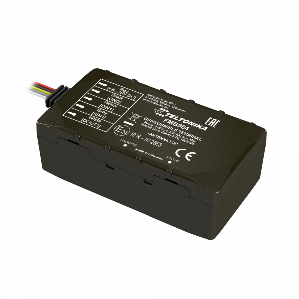
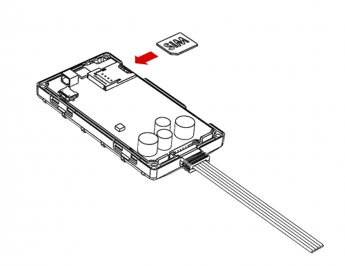
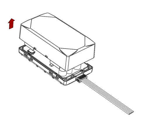
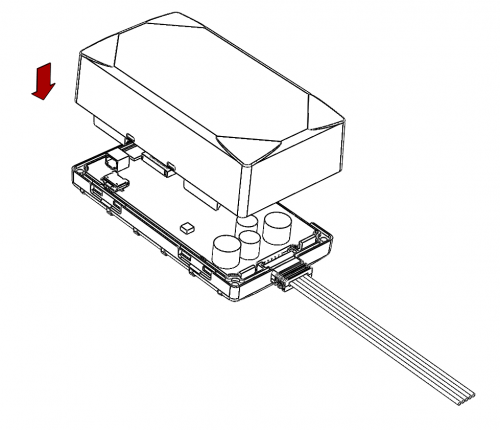
How to insert micro SIM card into FMB964
1. Remove FMB964 cover.
2. Insert SIM card as shown.
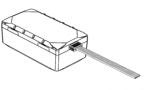
3. Attach cover.
4. Device is ready to be connected.
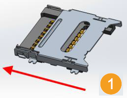
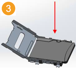
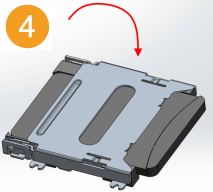
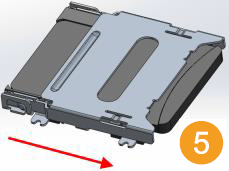
How to insert SD card into FMB964
1. Push microSD card lock case.
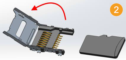
2. Open microSD card locker.
3. Correctly insert microSD card into slot.
4. Close microSD card locker.
5. Push microSD card lock case to locked position.
FMB964 device pinout
| Pin number | Pin name | Description |
|---|---|---|
| 1 | VCC (10-30)V DC (+) | Power supply (+10-30 V DC). |
| 2 | GND (-) | Ground. |
| 3 | DIN 1 | Digital input, channel 1. DEDICATED FOR IGNITION INPUT |
| 4 | AIN 1 | Analog input, channel 1. Input range: 0-30 V DC. |
| 5 | DOUT 1 | Digital output. Open collector output. Max. 3,3 A DC. |

