FMB640 UL202 Ultrasonic Fuel Sensor: Difference between revisions
| Line 27: | Line 27: | ||
To receive UL202 Fuel Sensor information to configured server, Ultrasonic UL202 Fuel level and status have to be enabled in “I/O” section. <br><br> | To receive UL202 Fuel Sensor information to configured server, Ultrasonic UL202 Fuel level and status have to be enabled in “I/O” section. <br><br> | ||
[[image:Ul_io.png]] | [[image:Ul_io.png]] | ||
==RS232 connection== | |||
RS232 Communication: The Yellow wire (TX) is connected with PIN6 RS232 Rx and the Blue wire (RX) is connected with PIN5 RS232 Tx. The Black wire (GND) connected to Teltonika GNSS device ground. <br><br> | |||
{| | |||
| [[File:Alert.png|left|link=|50px]] || <b>NOTE: RS232 is available on both PORT1 and PORT2</b> | |||
|} | |||
Revision as of 11:27, 22 July 2019
Introduction to the product
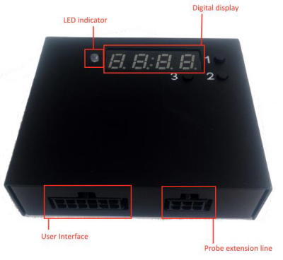
UL202 Ultrasonic Fuel Level Sensor connected to FMB640 using RS232 interface.
UL202
Definition of LED light:
• Green light on:
the probe works normally.
• Red light on:
the probe is abnormal (the probe line is not inserted or probe drops off).
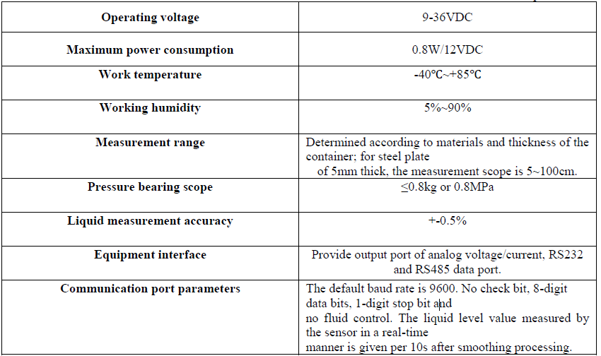
Ul202 sensor technical parameters:
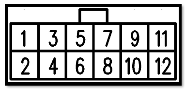
Port definition of user interface - User interface port is used to connect UL202 Ultrasonic Fuel Level Sensor connected to FMB640 using with RS232 interface
Installation
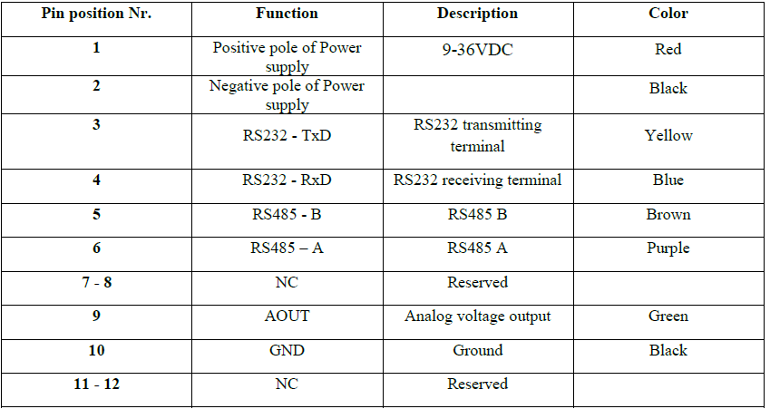
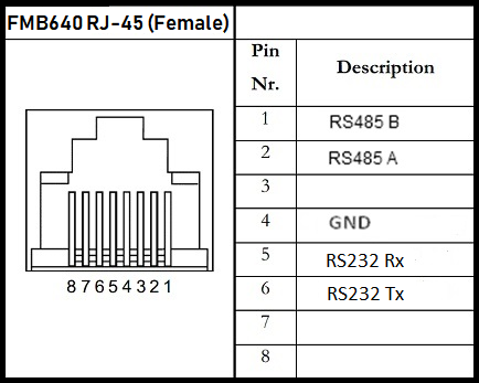
Before installation, make sure UL202 Ultrasonic Fuel Level Sensor is not powered ON. The RED and BLACK wires of User Interface line have to be connected to the Power Supply of the vehicle with RED wire connecting the positive role and BLACK wire connecting the ground. UL202 has RS232 serial port output:
FMB640 configuration
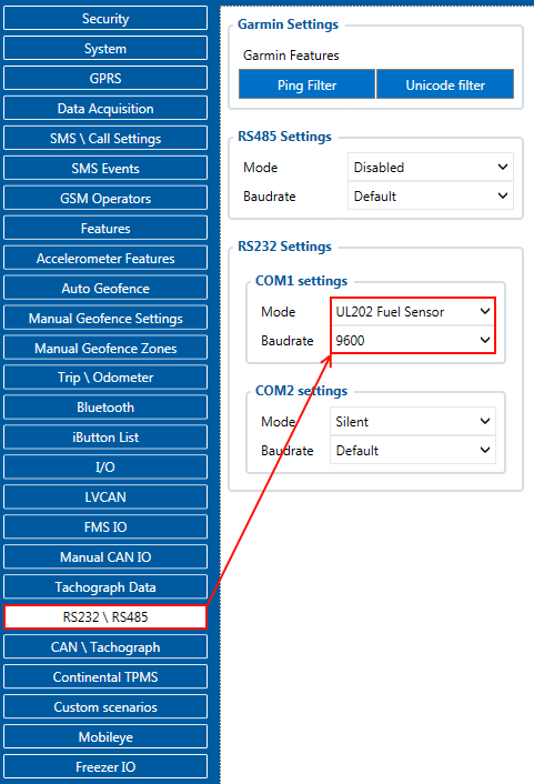
In order to configurate FMB640 to read UL202 Fuel Sensor information, COM1/2 port have to be selected as “UL202-2 Fuel Sensor”. Default baudrate is 9600.
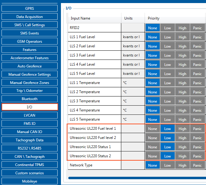
To receive UL202 Fuel Sensor information to configured server, Ultrasonic UL202 Fuel level and status have to be enabled in “I/O” section.
RS232 connection
RS232 Communication: The Yellow wire (TX) is connected with PIN6 RS232 Rx and the Blue wire (RX) is connected with PIN5 RS232 Tx. The Black wire (GND) connected to Teltonika GNSS device ground.
| NOTE: RS232 is available on both PORT1 and PORT2 |

