FMB630 CAN: Difference between revisions
No edit summary |
No edit summary |
||
| Line 1: | Line 1: | ||
__TOC__ | |||
CAN - Controller Area Network (CAN or CAN-bus) is a computer network protocol and bus standard designed to allow microcontrollers and devices to communicate with each other and without a host computer. | CAN - Controller Area Network (CAN or CAN-bus) is a computer network protocol and bus standard designed to allow microcontrollers and devices to communicate with each other and without a host computer. | ||
=AutoCAN= | |||
{{Template:FMB630_AutoCAN|model=FMB630|image1=[[Image:FMB630_autoCAN1.png|center|200px]]|image2=[[Image:FMB630_autoCAN2.png|center|250px]]|image3=[[Image:FMB630_autoCAN3.png|center|750px]]}} | |||
=Manual CAN= | |||
{{Template:FMB630_Manual_CAN|model=FMB630}} | |||
[[Category:FMB630 Configuration]] | [[Category:FMB630 Configuration]] | ||
Revision as of 11:38, 31 October 2019
Main Page > EOL Products > FMB630 > FMB630 Configuration > FMB630 CANCAN - Controller Area Network (CAN or CAN-bus) is a computer network protocol and bus standard designed to allow microcontrollers and devices to communicate with each other and without a host computer.
AutoCAN
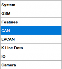
AutoCAN function allows user to automatically scan for available messages on CAN bus and configure CAN data sending to server. In order to configure AutoCAN connect FMB630 to computer with Port ½ cable. Launch FMB630 configurator version 1.1.1.7 or higher. Push “Connect“ button, then „CAN“ button. CAN configuration menu will be opened.
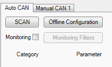
- SCAN - scans once for available messages on CAN bus;
- Monitoring – toggles scanning of messages on CAN bus every 3 seconds;
- Offline Configuration – enables CAN configuration when FMB630 is not connected to CAN bus;
- Auto CAN tab – configure CAN by selecting available messages from CAN bus;
- Manual CAN tab – Configure CAN by manually entering CAN message ID and data mask;
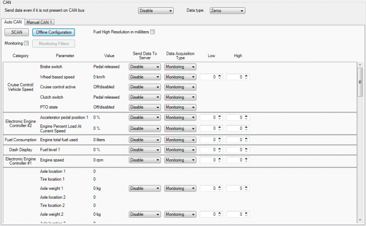
To start CAN configuration push “SCAN“ button. A table of all available CAN messages will appear. Description of columns:
- Category – shows CAN message;
- Parameter – shows configurable parameter name;
- Value – shows scanned value of parameter;
- Send data to server – allows to choose the type of data when it‘s generated:
○ Disabled – Data will not be collected;
○ On low priority – records will be generated as low priority events;
○ On high priority – records will be generated as high priority events and immediately sent to server via GPRS (if GPRS is available);
○ On panic - records will be generated as panic priority events and immediately sent to server via GPRS, if GPRS is not available records will be sent via SMS messages;
- Data acquisition type – allows to choose when records are generated:
○ Monitoring – monitors data;
○ On change – record is generated when parameter value is changed;
○ Hysteresis – record is generated when increasing parameter value becomes higher than High value, and decreasing becomes less than Low value;
○ Event on exit – record is generated when parameter value becomes higher than High value or lower than Low value;
○ Event on entrance – record is generated when parameter value becomes between High and Low values;
○ Event on both – record is generated when parameter value crosses High or Low values;
- Low – allows to choose low value for Data acquisition;
- High – allows to choose High level for Data acquisition;
CAN monitoring
To start CAN bus monitoring mark Monitoring check box. Table of available CAN messages will appear. Data from CAN bus will be updated every 3 seconds. In order to see only desired data open “Monitoring filters” menu.
Monitoring filters
Monitoring filters menu allows choosing which data will be shown in configuration menu. To enable/disable particular data monitoring use checkbox next to data name. To enable all data monitoring click Select all, to disable all data monitoring click Select none.
Note: CAN monitoring is FMB630 configurator function; it does not enable data sending to server. In order to configure data sending to server refer to Configuration section.
Manual CAN
Controller Area Network (CAN or CAN-bus) is a computer network protocol and bus standard designed to allow microcontrollers and devices to communicate with each other and without a host computer. It was designed specifically for automotive applications but is now also used in other areas.
SAE J1939 and J1708* is the vehicle bus standard used for communication and diagnostics among vehicle components. Based on the same architecture FMS protocol dedicated to telematics systems is available. It has certain standardized parameters available, such as fuel consumption, engine work-hours, etc. Please visit http://www.fms-standard.com/ for more information and message structure.
The FMS-interface is an optional interface of different truck manufacturers. Supported information is dependent upon vehicle equipment. For the full information set, additional Electronic Control Units (ECU) may be required. Please contact the manufacturer or your dealer for more details.
Vehicle brands supported:
• Mercedes Benz
• Volvo
• MAN
• DAF
• Iveco
• Scania
• Renault
Available parameters:
• Total Fuel
• Total Distance
• Status of brake pedal *
• Engine Torque *
• Actual fuel
• Accelerator pedal position *
• Status engine brake
• Speed *
• RPM
• Engine hours
• Vehicle Weight *
• Fuel level
• Tachograph data *
Availability of parameter depends on vehicle’s model and configuration of FMS interface of the truck. J1708 is additional FMS protocol used by some vehicle manufacturers. If your vehicle supports J1939 and J1708 both protocols then you must disable J1708 in configuration to receive fuel data.
General description
- CAN works if no USB cable is inserted and isn’t in deep sleep mode;
- Uses six different speeds: 50 kbps, 100 kbps, 125 kbps, 250 kbps, 500 kbps, 1000kbps;
- Auto Baud rate detection;
- Filtering messages (StId, ExtId) according to configuration;
- Using mask, filters required bytes;
- Different CAN configurations.
Configuration
Manual CAN data can be configured using “Manual CAN” in CAN tab.
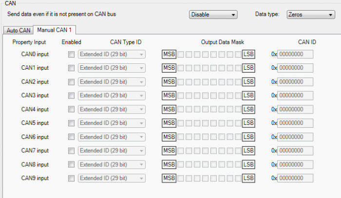
CAN message ID type: Message ID type two types according to SAEJ1939 standard: Standard ID (value: 0 to 0x7FFh) and Extended ID (value: 0 to 0x1FFFFFFFh).

Message ID value is entered in hex format. This parameter is used to configure hardware message filter. All messages contain 8 bytes of data, to select particular data/bytes “Output Data Mask” is used, it’s done by ticking required bytes, only selected bytes are sent to server.

Example A sample CAN message has the following structure: X18FEE9018FFFFFFFF23840300, where essential parts are ‘FEE9’ – identifier and ‘FFFFFFFF23840300’ – data bytes. CAN messages are configured like any other I/O parameters. They consist of 4 identifier bytes and 8 data bytes. Below you will find a sample configuration for fuel consumption parameter: ID type – is always 29 bits. Output data mask – defines which data bytes are sent to the server (sometimes not all data bytes are necessary). CAN ID – this is 4 byte identifier. Messages use 4 bytes, but the first and last bytes may differ in different vehicle models while the middle four bytes are the same for all vehicles. The first and last bytes may have any value. Because of this reason it is recommended to write FF in the first byte and the same in the last byte.
This information is provided only as an example and Teltonika
takes no responsibility for information accuracy or damage that may be done to the vehicle or FMB630 module while integrating it.
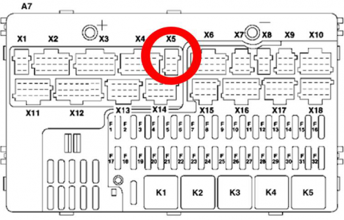
Example: All Mercedes Benz Actros 2 models with Vehicle Identification Number (VIN) starting with WDB93 have a possibility to connect FMB630 module to CAN bus. This can be done by connecting to special PSM module (which may or may not be included in the truck) or ground module of the vehicle. For CAN signal to be available, parameter 520 must be enabled in “kommunikationsschnittstelle” in the vehicle with Mercedes Stardiagnose. CAN wires can be found on X5 connector located in the fuse box: Pin 5: CAN Low signal (yellow wire) Pin 2: CAN High signal (blue wire)
In the example FMB630 will filter all CAN messages with identifier FFFEE9FF (fuel consumption).

CAN parameter configuration example
Note: Averaging constant cannot be used with CAN data, because this information comes in digital format. So in order to prevent data loss, set Averaging constant parameter to 1.
Most parameters have certain resolution. FEE9 parameter has 0.5L/bit gain, so value that is sent to server has to be multiplied by 0.5. Data parsing is preceded by selecting correct message from all available on CAN bus. FMS standard interface description indicates that fuel consumption is parameter with ID FEE9:
| 00FEE9 | PGN HEX | |||||||
|---|---|---|---|---|---|---|---|---|
| 65,257 | PGN | |||||||
| 1000 ms | Rep. Rate | |||||||
| Data Byte 1 | Data Byte 2 | Data Byte 3 | Data Byte 4 | Data Byte 5 | Data Byte 6 | Data Byte 7 | Data Byte 8 | Byte No. |
| Not used for FMS- Standard |
Not used for FMS- Standard |
Not used for FMS- Standard |
Not used for FMS- Standard |
Total fuel used 0,5 L/Bit gain |
Total fuel used 0,5 L/Bit gain |
Total fuel used 0,5 L/Bit gain |
Total fuel used 0,5 L/Bit gain |
Name Values |
The example indicates how fuel consumption message is selected and how configuration impacts this selection.
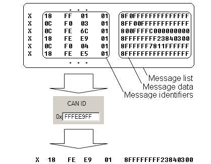
When certain message is filtered, FMB630 checks which data bytes should be sent to server. Document indicates that 5-8 bytes are used in FMS standard.
| Data Byte 5 | Data Byte 6 | Data Byte 7 | Data Byte 8 | Byte No. | ||||||||||||||||||||||||||||
|---|---|---|---|---|---|---|---|---|---|---|---|---|---|---|---|---|---|---|---|---|---|---|---|---|---|---|---|---|---|---|---|---|
| 8 | 7 | 6 | 5 | 4 | 3 | 2 | 1 | 8 | 7 | 6 | 5 | 4 | 3 | 2 | 1 | 8 | 7 | 6 | 5 | 4 | 3 | 2 | 1 | 8 | 7 | 6 | 5 | 4 | 3 | 2 | 1 | Bit no |
| Total fuel used | Total fuel used | Total fuel used | Total fuel used | Name | ||||||||||||||||||||||||||||
| 0,5 L/Bit gain | 0,5 L/Bit gain | 0,5 L/Bit gain | 0,5 L/Bit gain | Values | ||||||||||||||||||||||||||||
| 0 L offset | 0 L offset | 0 L offset | 0 L offset | Values | ||||||||||||||||||||||||||||
| 5.2.5.66 | 5.2.5.66 | 5.2.5.66 | 5.2.5.66 | SAE ref | ||||||||||||||||||||||||||||
| SPN 250 | SPN 250 | SPN 250 | SPN 250 | SPN | ||||||||||||||||||||||||||||
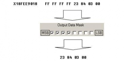
Data bytes are filtered by selecting the checkboxes in Output data mask. Note, that configurator has them listed starting with MSB. After message is filtered it is attached to the data packet and sent to the server. Values are returned in HEX. 00 03 84 23(HEX) = 230435(DEC). Notice, that data resolution is 0.5L/bit gain – value has to be multiplied by 0.5, therefore vehicle used a total 115217,5 liters of fuel.
