Template:FM36 socket pinout: Difference between revisions
Appearance
Created page with "=='''2x6 socket pinout'''== {| class="wikitable" |+ ! style="width:10%; border: 1px solid white; border-bottom: 2px solid #0054A6; background: white; color: #0054A6; text-a..." |
|||
| Line 13: | Line 13: | ||
|- | |- | ||
| style="border: 1px solid white; border-bottom: 2px solid #E8E8E8; text-align: left; vertical-align: center; background: white;"| 2 | | style="border: 1px solid white; border-bottom: 2px solid #E8E8E8; text-align: left; vertical-align: center; background: white;"| 2 | ||
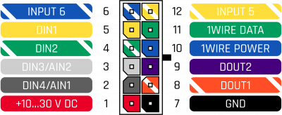
| style="border: 1px solid white; border-bottom: 2px solid #E8E8E8; text-align: left; vertical-align: center; background: white;"| AIN 1 | | style="border: 1px solid white; border-bottom: 2px solid #E8E8E8; text-align: left; vertical-align: center; background: white;"| DIN 4 / AIN 1 | ||
| style="border: 1px solid white; border-bottom: 2px solid #E8E8E8; text-align: left; vertical-align: center; background: white;"| Analog input, channel 1. Input range: 0-30 V DC / Digital input, channel 4. | | style="border: 1px solid white; border-bottom: 2px solid #E8E8E8; text-align: left; vertical-align: center; background: white;"| Analog input, channel 1. Input range: 0-30 V DC / Digital input, channel 4. | ||
|- | |- | ||
| style="border: 1px solid white; border-bottom: 2px solid #E8E8E8; text-align: left; vertical-align: center; background: white;"| 3 | | style="border: 1px solid white; border-bottom: 2px solid #E8E8E8; text-align: left; vertical-align: center; background: white;"| 3 | ||
| style="border: 1px solid white; border-bottom: 2px solid #E8E8E8; text-align: left; vertical-align: center; background: white;"| AIN 2 | | style="border: 1px solid white; border-bottom: 2px solid #E8E8E8; text-align: left; vertical-align: center; background: white;"| DIN 3 / AIN 2 | ||
| style="border: 1px solid white; border-bottom: 2px solid #E8E8E8; text-align: left; vertical-align: center; background: white;"| Analog input, channel 2. Input range: 0-30 V DC / Digital input, channel 3. | | style="border: 1px solid white; border-bottom: 2px solid #E8E8E8; text-align: left; vertical-align: center; background: white;"| Analog input, channel 2. Input range: 0-30 V DC / Digital input, channel 3. | ||
|- | |- | ||

