Template:FMB208 First start card: Difference between revisions
Appearance
Kudalevas.da (talk | contribs) No edit summary |
No edit summary |
||
| Line 8: | Line 8: | ||
=='''How to insert {{{sim_type|Micro-}}}SIM card {{{battery|and connect the battery}}}'''== | |||
# '''Unscrew''' 6 screws counterclockwise that are located on the '''bottom''' of the {{{model|FMB208}}} device. | |||
# Remove the '''cover'''. | |||
# Insert '''{{{sim_type|Micro-}}}SIM''' card as shown with '''PIN request disabled''' or read '''[[{{{model|FMB208}}} Security info|Security info]]''' how to enter it later in [[Teltonika Configurator]]. Make sure that {{{sim_type|Micro-}}}SIM card '''cut-off corner''' is pointing forward to slot. | |||
# Connect '''battery''' as shown to device. | |||
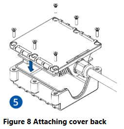
# After '''configuration''', see “'''[[{{{model|FMB208}}}_First_Start#PC Connection (Windows)|PC Connection (Windows)]]'''”, attach device '''cover''' back and '''screw''' in all screws. | |||
Device is ready to be mounted. | |||
[[Image:{{{Unscrew_pic1|FMB208_cover_1.png}}}|260px]][[Image:{{{Remove_the_cover_pic2|FMB208_cover_2.png}}}|260px]][[Image:{{{sim_insert_pic3|FMB208_cover_3.png}}}|260px]][[Image:{{{battery_pic4|FMB208_cover_4.png}}}|260px]][[Image:{{{screw_pic4|FMB208_cover_5.png}}}|260px]] | |||
{| | |||
|- | |||
| [[File:Alert.png|left|link=]] || <b>{{{sim_type|Micro-}}}SIM card insertion/removal must be performed when device is powered off – external voltage {{{battery|and internal battery}}} disconnected. Otherwise {{{sim_type|Micro-}}}SIM card might be damaged or device will not detect it.</b> | |||
|} | |||
Revision as of 11:44, 15 December 2020
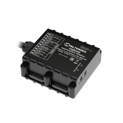
FMB208 Teltonika FMB208 is a SPECIAL waterproof tracker with Bluetooth connectivity and integrated backup battery. Device was designed to meet Indian government regulation AIS 140
How to insert Micro-SIM card and connect the battery
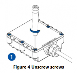
- Unscrew 6 screws counterclockwise that are located on the bottom of the FMB208 device.
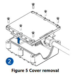
- Remove the cover.
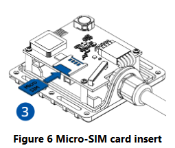
- Insert Micro-SIM card as shown with PIN request disabled or read Security info how to enter it later in Teltonika Configurator. Make sure that Micro-SIM card cut-off corner is pointing forward to slot.
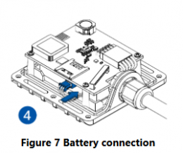
- Connect battery as shown to device.
- After configuration, see “PC Connection (Windows)”, attach device cover back and screw in all screws.
Device is ready to be mounted.
 |
Micro-SIM card insertion/removal must be performed when device is powered off – external voltage and internal battery disconnected. Otherwise Micro-SIM card might be damaged or device will not detect it. |

