MSP500 RS-232: Difference between revisions
| Line 67: | Line 67: | ||
====RS232 POS printer==== | ====RS232 POS printer==== | ||
[[Image:RS-232 POS Printer. | [[Image:RS-232 POS Printer.gif]] | ||
The '''5803 Bluetooth printer''' tested & confirmed working on command set. | The '''5803 Bluetooth printer''' tested & confirmed working on command set. | ||
Revision as of 11:32, 13 April 2021
Main Page > EOL Products > MSP500 > MSP500 Manual > MSP500 RS-232RS-232 Interface
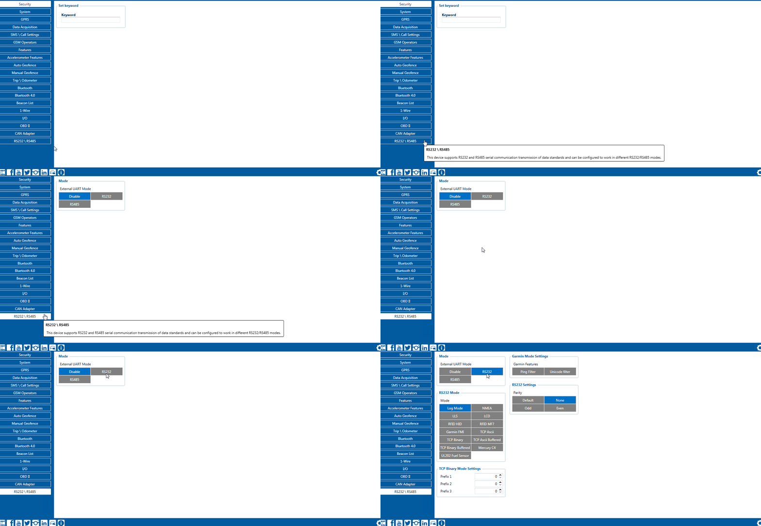
RS-232 supports full-duplex communication which means the data can be both sent and received at the same time as they use separate transmission lines. Most of the modes are the same as for RS-485. MSP500 RS-232 connection diagram is shown on the figure above.
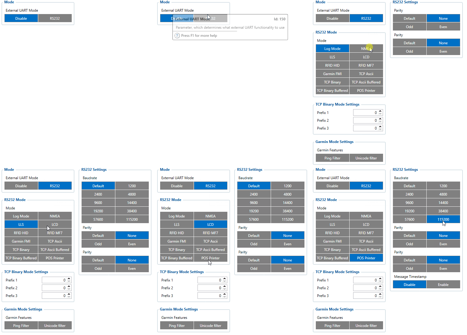
RS-232 modes
Log mode, NMEA, LLS, TCP ASCII and TCP Binary modes are identical to those of RS-485. In RS-232 LLS mode only one LLS fuel level sensor can be connected. Additionally TCP ASCII Buffered and TCP Binary Buffered modes are available.
- RS-232 LCD mode:
In this mode user is able to communicate with the server through terminal. A link between FMB device and the server has to be established for this mode to function properly.
- RS-232 RFID HID/RFID MF7 mode:
The difference between RFID HID Mode and RFID MF7 Mode is that in RFID MF7 Mode FMB125 understands RFID messages that are in hexadecimal text format and RFID HID Mode interpretes messages that are in binary format. The type of RFID message sent to FMB125 depends on the RFID reader. For example, RFID MF7 mode message looks like "$aa$02$03$04$17$89$00$01" while HID mode message is of following format: "1213141519".
The selected mode has to correspond to the RFID reader's mode.
 Please contact your local sales representative for more information about RFID IDs and devices.
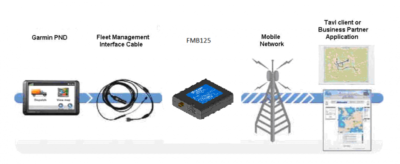
- RS-232 Garmin mode:
Garmin provides a Fleet Management Interface Tool Kit, once FMB125 is connected to the navigator it enables the driver to have a "screen" in their vehicle for real-time navigation and messaging, and offers job dispatch capabilities to help them be more efficient.
FMB125 and Garmin operational diagram is shown on the figure below.

- RS-232 TCP Binary/TCP ASCII mode:
In TCP ASCII/Binary mode all data received from external device is sent directly to server. Data is encapsulated in codec 12 format. TCP Binary Mode has a delay of 30 ms, if no data is received for 30 ms, data is sent to the server. TCP ASCII mode waits for the End of Line (EOL) character (0x0D0A, \r\n) to pack data and send it to the server
- RS-232 TCP Binary Buffered/TCP ASCII Buffered mode:
TCP ASCII Buffered and TCP Binary Buffered modes are used to collect data from RS232 and save it in buffer if there is no link with server and data cannot be sent immediately. When link is established and there is data to transmit, then RS232 data from buffer is transmitted after all records are sent. Data is sent in codec 13 protocol.
Note. That in TCP ASCII and TCP Binary modes device sends data from external device only to main server. In Buffered modes – to both main and backup/duplicate servers.
Message timestamp:
Message Timestamp parameter is used to determine if it is necessary to include timestamp in RS232 TCP packet when sending to server. If parameter is enabled, then Codec 13 is used for data sending. Otherwise, Codec 12 is used.
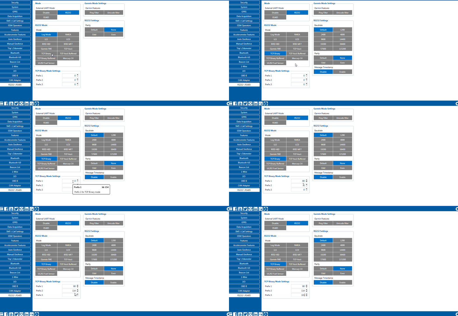
RS-232 TCP Binary settings
TCP Binary has a setting Prefix. It is possible to set Prefix 1, Prefix 2 or Prefix 3. These prefixes can be used seperately or in unison. To configure this setting a value from 0 to 255 in decimal has to be entered. Device will convert this value to HEX and compare the 1st, 2nd or 3rd byte from incoming data. If the values do not match, device will not accept incoming data.
Example:
Incoming packet through RS232/RS485 using TCP Binary/TCP Binary Buffered mode - 50 72 65 66 69 78 20 57 6f 72 6b 69 6e 67
- If Prefix 1 is set to 80 in decimal, it is equal to 50 in HEX.
- FMB device will then check the 1st byte of incoming data and compare to the set Prefix 1.
- If Prefix 2 is set to 114 in decimal, it is equal to 72 in HEX.
- FMB device will then check the 2nd byte of incoming data and compare to the set Prefix 2.
- If Prefix 3 is set to 101 in decimal, it is equal to 65 in HEX.
- FMB device will then check the 3rd byte of incoming data and compare to the set Prefix 3.
When values match, data will be accepted and saved to Buffer (using TCP Binary Buffered mode) or sent to server (using TCP Binary mode).
Incoming packet through RS232/RS485 using TCP Binary/TCP Binary Buffered mode - 50 0 65 66 69 78 20 57 6f 72 6b 69 6e 67
- If Prefix 1 is set to 80 in decimal, it is equal to 50 in HEX.
- FMB device will then check the 1st byte of incoming data and compare to the set Prefix 1.
- If Prefix 2 is set to 114 in decimal, it is equal to 72 in HEX.
- FMB device will then check the 2nd byte 0 of incoming data and compare to the set Prefix 2.
Since Prefix 2 does not match incoming 2nd byte, data will not be accepted.
RS232 POS printer
The 5803 Bluetooth printer tested & confirmed working on command set.
Before every print, a status command byte request is sent. If the device returns the byte within a specific time frame, it means that the device is present. If cleanup task is not running “Get real-time status” command is sent every second to check if printer was connected to MSP500 device. Upon successful detection of a connected printer MSP500 starts printing all the records generated within the last hour.
Commands are sent in this format:
   1 byte - Beginning of the command (ESC, GS or similar type byte from ASCII table)
   1-2 byte(-s) - (optional) Command identifier
   (x) bytes - (optional) Command arguments
Text printing is accomplished by just sending plain ASCII without any commands. If the buffer for the whole print line fills up (>32 chars), it prints the text automatically and feeds one line. If there’s less text, than it only prints and feeds line when linefeed (carriage is not needed) char is sent. Very few commands give back an answer (only status commands from all the tested ones).
Please contact your sales representative if there is need for the full commands list provided.
Garmin protocols
The following is a list of protocols supported and the corresponding list of features/benefits. MSP500 can fully support Fleet Management Interface (FMI) versions up to 2.1. Other or higher versions may be supported, but Teltonika is not responsible for the changes made by Garmin, which may affect the function of MSP500 and Garmin products. For more information about Garmin products and FMI versions, please refer to https://www.garmin.com/en-US/fleet-ready-navigators/. Notice that some Garmin products use different connection cables than others.
Standard protocols
Text Message Protocol:
- Allows text messages sent to the device to be displayed in "inbox" on navigation unit;
- Garmin can provide a confirmation that message was read;
- Garmin can also provide a yes/no box below the text of the message to enable a quicker response;
- Messages can be up to 199 characters long;
- Messages can also be generated from device and sent to dispatcher/office;
- Messages received will be notified to driver through a pop-up alert on Garmin screen;
- Garmin provides a "virtual keyboard" for text communication.
Stop (Destination) Protocol:
- Garmin can display a list of Stops/Jobs reported to the device in a separate category called "My Stops";
- Driver has ability to navigate directly to Stop from the list;
- Garmin can provide status of a current Stop in progress;
- Garmin can indicate whether the driver has stopped at the location;
- Garmin can inform how far the driver has progressed through the list of Stops;
- Garmin can provide confirmation that the driver has received a particular Stop, familiarized himself/herself with its details or removed it from the list;
- Can provide confirmation that a Stop has been reached.
Estimated Time of Arrival Protocol:
- Dispatcher/office can request the ETA of the current Stop/job in progress;
- Garmin can notify about the actual time of arrival as well as the distance remaining to a Stop.
Auto-Arrival at Stop Protocol:
- This feature is used to tell Garmin PND to automatically detect that it has arrived at a Stop and then to prompt the driver if he/she would like to mark the Stop as done and begin navigating to a next Stop on the list;
- Auto-arrival can be determined by how long the unit is stopped close to the destination (in the case driver has to park and walk) or by how close the unit needs to be to the destination before the Auto-arrival feature is activated.
Data Deletion Protocol:
- Dispatcher/office has the ability to wipe clean the data on Garmin PND;
- It allows to clean messages in inbox and remove stops.
Enhanced protocols
Canned Responses/Messages:
- Fleet managers can communicate by sending up to 200 "canned" responses from the server to be stored directly on Garmin devices;
- Up to 50 of these canned responses can be utilized for any given scenarios;
- Drivers can store up to 120 canned messages, eliminating the need to type while driving.
Status Protocol:
- Up-to-the-minute communications that allow drivers to automatically send status updates;
- Driver's units can store up to 16 status indicators such as start/stop shift, on/off break etc.
Supported features on TAVL client application
TAVL client application lets user use the following features of Garmin FMI:
- Text messaging;
- Destination message;
- ETA request.
Text messaging
Text messaging feature lets user communicate with the driver (user that operates Garmin device) by sending text messages via GPRS.
Destination message
Destination message is used to inform the driver of a new destination. When Garmin device receives a destination message from the server it displays it as a Stop to the driver and also gives the driver an ability to start navigating to the Stop location. New destination in TAVL client is represented as a Geozone so a new Geozone (as destination) has to be created first.
ETA request message
Estimated Time of Arrival request message is used when user wants to know an expected arrival time to currently active destination and the distance (in meters) from current object location to the destination.


