Making Custom BLE Sensor configuration and preset: Difference between revisions
Created page with "== Introduction == First thing you have to know before configuring a sensor is data protocol. Without data protocol you can only attempt to extract raw data from the sensor,..." |
m Protected "Making Custom BLE Sensor configuration and preset": Excessive vandalism ([Edit=Allow only administrators] (indefinite) [Move=Allow only administrators] (indefinite)) [cascading] |
(No difference)
| |
Revision as of 10:43, 20 April 2021
Main Page > Frequently Asked Questions - FAQ > Making Custom BLE Sensor configuration and presetIntroduction
First thing you have to know before configuring a sensor is data protocol.
Without data protocol you can only attempt to extract raw data from the sensor, by configuring to save all the data sent by sensor into IO elements.
Extracting RAW data
In below examples we are trying to extract data from two TOPFLYtech BLE 5.0 sensors:
1) temperature, humidity and light sensor.
2) door, temperature sensor.
Prerequisites:
1.BT radio enabled in Bluetooth section of configurator.
2.Codec8extedended set in System section of configurator.
To save sensor incoming data to IO you should configure:
MAC = MAC of the sensor -> needed to establish connection with the sensor.
Type = FE -> any.
Data Size = 128B -> maximum available in IO.
Action = Save -> save to IO element.
IO = custom -> We do not know the protocol yet, so we use custom that can be used for HEX data.
IO tab of configurator: enable BLE custom X where X is the sensor number in Bluetooth 4.0 section.
*Note: you might have to configure more rows if sensor is sending more than 128B of data.
Once we save the configuration and observe records made by the device we will see that AVL ID for BLE custom 1 will have raw sensor data:
0x1416FFBF1002140EFEBF9D7A7A4164090E350001000509636F6C64
Parsing Data according to protocol Example 1
We can parse this according to the protocols provided by the vendor/manufacturer of the sensor, if not provided during the purchase please contact the vendor for the protocol. Full protocol document for our example can be found here:File:Protocol.xlsx
Raw data assigned to corresponding protocol parts:
| Message Header | Hardware Version | Firmware Version | ID | Battery (%) | Temperature (℃) | Humidity (%) | Ambient Light Status | Alarm | Length | Sesnor Name Header | Sesnor Name | ||
| 1416FFBF1002 | 14 | 0E | FEBF9D7A7A41 | 64 | 09 | 0E | 35 | 00 | 01 | 00 | 05 | 09 | 636F6C64 |
Parsed raw data:
| Protocol explanation | Raw data | Parsed Data | |
| Message Header | 1416FFBF1002 | Fixed value | |
| Hardware Version | 14 | Version 1.4 | |
| Firmware Version | 0E | Version 14 | |
| ID | FEBF9D7A7A41 | ID=MAC=FEBF9D7A7A41 | |
| Battery (%) | 64 | 64(Hex)=100(Dec)
Then battery percent=100% | |
| Temperature (℃) | 09 | 0E | 09 0E(Hex) to BIN:
0000 1001 0000 1110 Bit 15=0, + Bit 15=1, - Bit 15 is 0, so it's positive temperature Bit 0-Bit14, temperature valueBit 0-14 convert to DEC is 2318 Then 2318/100=23.18 The temperature is +23.18℃ |
| Humidity (%) | 35 | 35(Hex)=53(DEC)
The humidity is 53% | |
| Ambient Light Status | 00 | 01 | Fixed Value=0
01=light on It means the sensor environment has light |
| Alarm | 00 | 00 = this is not a alarm message.
01: alarm 02: high temperature alarm 04: low temperature alarm 06: low battery alarm | |
| Length | 05 | 05=there are 5 bytes from byte 23
the length will be changed depending on sensor name. The sensor name is max 8 bytes. So the max length value is 09 | |
| Sesnor Name Header | 09 | Fixed Value | |
| Sesnor Name | 636F6C64 | Convert Hex to ASCII
63=C 6F=O 6C=L 64=D So the sensor name is cold | |
According to the data from the sensor, available IO elements, you can create a preset for the sensor.
In our case we are interested in battery level, humidity and temperature.
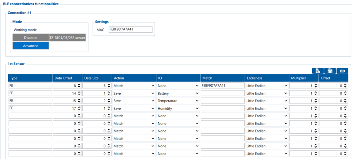
We select all type fields to be FE, data offset and size is calculated according to the protocol, visual example below:
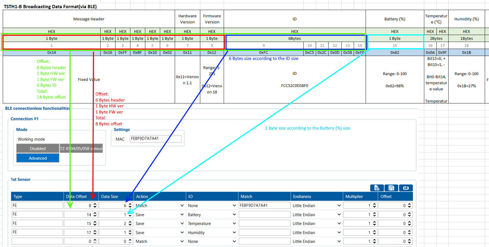 *Note: Match field is not necessary for every sensor, it's used when sensor sends few different structure packets to match the packet needed.
If you specify the match field, make sure that sensor does not have dynamic (variable) information in protocols for matched data otherwise it might be filtered until it matches exact value specified in the match field.
| Protocol explanation | Raw data | Type | Offset | Size | Action | IO | |
| Message Header | 1416FFBF1002 | 6 | 6 | ||||
| Hardware Version | 14 | 1 | 1 | ||||
| Firmware Version | 0E | 1 | 1 | ||||
| ID | FEBF9D7A7A41 | FE | 6+1+1=8 | 6 | Match | None | |
| Battery (%) | 64 | FE | 8+6=14 | 1 | Save | Battery | |
| Temperature (℃) | 09 | 0E | FE | 15 | 2 | Save | Temperature |
| Humidity (%) | 35 | FE | 17 | 1 | Save | Humidity | |
| Ambient Light Status | 00 | 01 | |||||
| Alarm | 00 | ||||||
| Length | 05 | ||||||
| Sesnor Name Header | 09 | ||||||
| Sesnor Name | 636F6C64 | ||||||
Once everything is configured it should look as follows:
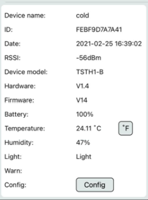
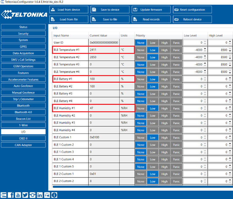
Pictures of the sensor being read in the sensor app and configurator:
In app:
In configurator:
Parsing Data according to protocol Example 2
Raw sensor data:
0x1216FFBF0E04120EFF779695EE4B640A730100080954534454312D42
Raw data assigned to corresponding protocol parts:
| Message Header | Hardware Version | Firmware Version | ID | Battery (%) | Temperature (℃) | Door Status | Alarm | Length | Sesnor Name Header | Sesnor Name | |||||||||||
| 1216FFBF0E04 | 12 | 0E | FF779695EE4B | 64 | 0A73 | 01 | 00 | 08 | 09 | 54534454312D42 | |||||||||||
Parsed raw data:
| Protocol explanation | Raw data | Parsed Data | |
| Message Header | 1216FFBF0E04 | Fixed value | |
| Hardware Version | 12 | Version 1.2 | |
| Firmware Version | 0E | Version 14 | |
| ID | FF779695EE4B | ID=MAC=FF779695EE4B | |
| Battery (%) | 64 | 64(Hex)=100(Dec)
Then battery percent=100% | |
| Temperature (℃) | 0A | 73 | 09 0E(Hex) to BIN:
0000 1010 0111 0011 Bit 15=0, + Bit 15=1, - Bit 15 is 0, so it's positive temperature Bit 0 - Bit 14, temperature valueBit 0 - Bit 14 convert to DEC is 2675 Then 2775/100=26.75 The temperature is +26.75℃ |
| Door Status | 01 | 01 = Door open
0x01 = Door Open | |
| Alarm | 00 | 00 = this is not a alarm message.
01: alarm 02: high temperature alarm 04: low temperature alarm 06: low battery alarm | |
| Length | 08 | 05=there are 5 bytes from byte 23
the length will be changed depending on sensor name. The sensor name is max 8 bytes. So the max length value is 09 | |
| Sesnor Name Header | 09 | Fixed Value | |
| Sesnor Name | 54534454312D42 | Convert Hex to ASCII
So the sensor name is TSDT1-B | |
Once everything is configured it should look as follows:
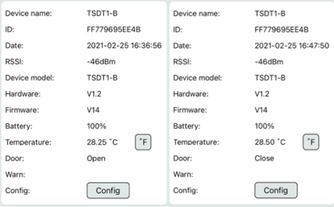
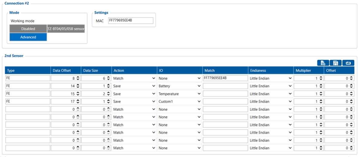 Pictures of the sensor being read in the sensor app and configurator:
In app:
in configurator:
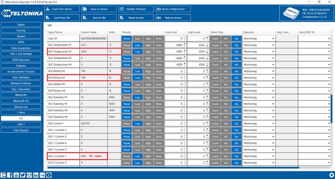
Door open:
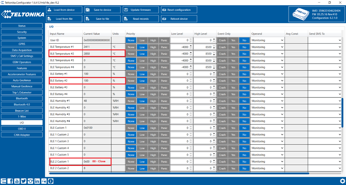
Door closed:
Creating Presets
After configuration is finished you can save preset, using save button:
Saved presets are found at:
C:\Users\<your username>\Documents\Presets
They can be shared with other engineers, they just have to save the received preset to same location C:\Users\<your username>\Documents\Presets to be able to load it in the configurator.
Including Presets in next base configurator release
On client's request or based on TPS insights about client's use case, it might be needed to add the sensors to our available presets with next configurator release. Check with your sales manager about the conditions and information needed to include the preset on next release.


