FMB120 First Start: Difference between revisions
Atabasnikov (talk | contribs) mNo edit summary |
Atabasnikov (talk | contribs) mNo edit summary |
||
| Line 63: | Line 63: | ||
| style="text-align: left; background: #F6F6FB;" | 1 | | style="text-align: left; background: #F6F6FB;" | 1 | ||
| style="text-align: left; background: #F6F6FB;" | VCC (10-30)V DC (+) | | style="text-align: left; background: #F6F6FB;" | VCC (10-30)V DC (+) | ||
| style="text-align: left; background: #F6F6FB;" | Power supply (10-30 V DC). | | style="text-align: left; background: #F6F6FB;" | Power supply (+10-30 V DC). | ||
|- | |- | ||
| style="text-align: left; background: #F6F6FB;" | 2 | | style="text-align: left; background: #F6F6FB;" | 2 | ||
| style="text-align: left; background: #F6F6FB;" | AIN 1 | | style="text-align: left; background: #F6F6FB;" | AIN 1 | ||
| style="text-align: left; background: #F6F6FB;" | Analog input, channel 1. Input range: 0- | | style="text-align: left; background: #F6F6FB;" | Analog input, channel 1. Input range: 0-30 V DC. | ||
|- | |- | ||
| style="text-align: left; background: #F6F6FB;" | 3 | | style="text-align: left; background: #F6F6FB;" | 3 | ||
| style="text-align: left; background: #F6F6FB;" | AIN 2 / DIN 3 | | style="text-align: left; background: #F6F6FB;" | AIN 2 / DIN 3 | ||
| style="text-align: left; background: #F6F6FB;" | Analog input, channel 2. Input range: 0- | | style="text-align: left; background: #F6F6FB;" | Analog input, channel 2. Input range: 0-30 V DC / Digital input, channel 3. | ||
|- | |- | ||
| style="text-align: left; background: #F6F6FB;" | 4 | | style="text-align: left; background: #F6F6FB;" | 4 | ||
| Line 154: | Line 154: | ||
<font size="+3"><span style=color:#FF0000>'''Safety information'''</span></font><br/> | |||
<font size="+2"> | |||
This message contains information on how to operate FMB120 safely. By following these requirements and recommendations, you will avoid dangerous situations. You must read these instructions carefully and follow them strictly before operating the device!<br/> | |||
The device uses SELV limited power source. The nominal voltage is +12 V DC. The allowed range of voltage is +10-30 V DC.<br/> | |||
To avoid mechanical damage, it is advised to transport the device in an impact-proof package. Before usage, the device should be placed so that its LED indicators are visible, which show the status of device operation.<br/> | |||
When connecting the 2x6 connector wires to the vehicle, the appropriate jumpers of the vehicle power supply should be disconnected.<br/> | |||
Before unmounting the device from the vehicle, the 2x6 connector must be disconnected.</br> | |||
The device is designed to be mounted in a zone of limited access, which is inaccessible to the operator. All related devices must meet the requirements of EN 60950-1 standard.<br/> | |||
The device FMB120 is not designed as a navigational device for boats.<br/> | |||
</font> | |||
| Line 180: | Line 191: | ||
|- | |- | ||
| style="text-align: left; background: #F6F6FB;" | [[Image:Bw_ecute.png|50px]] | | style="text-align: left; background: #F6F6FB;" | [[Image:Bw_ecute.png|50px]] | ||
| style="text-align: left; background: #F6F6FB;" | | | style="text-align: left; background: #F6F6FB;" | Installation and/or handling during a lightning storm is prohibited. | ||
|} | |} | ||
</font> | </font> | ||
https://teltonika.lt/product/fmb120-internal-gnss-antenna-battery/ | https://teltonika.lt/product/fmb120-internal-gnss-antenna-battery/ | ||
Revision as of 09:24, 10 April 2018
Main Page > Advanced Trackers > FMB120 > FMB120 First Start
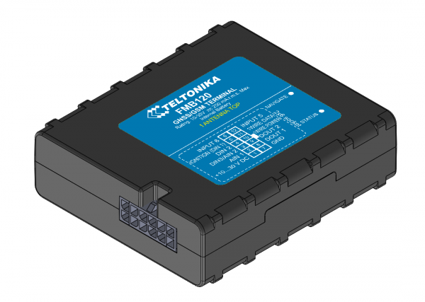
FMB120 GNSS/GSM/Bluetooth tracker with internal GNSS/GSM antennas and internal battery
Quick Start Guide
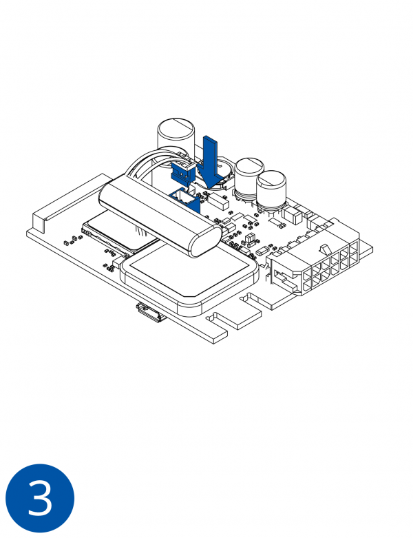
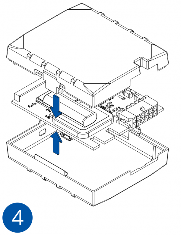
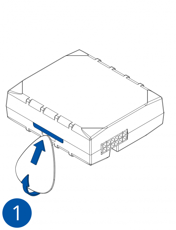
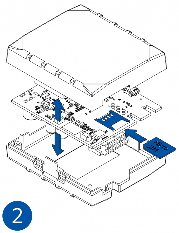
How to insert micro SIM card into FMB120
1. Remove FMB120 cover.
2. Insert SIM card as shown. SIM slot 1 is closer to PCB, SIM slot 2 is the upper one.
3. Attach cover.
4. Device is ready.
2x6 socket pinout

| Pin number | Pin name | Description |
|---|---|---|
| 1 | VCC (10-30)V DC (+) | Power supply (+10-30 V DC). |
| 2 | AIN 1 | Analog input, channel 1. Input range: 0-30 V DC. |
| 3 | AIN 2 / DIN 3 | Analog input, channel 2. Input range: 0-30 V DC / Digital input, channel 3. |
| 4 | DIN 2 | Digital input, channel 2. |
| 5 | DIN 1 | Digital input, channel 1. |
| 6 | INPUT 6 | TX EXT (LVCAN – TX). |
| 7 | GND (-) | Ground. |
| 8 | OUT 1 | Digital output, channel 1. Open collector output. Max. 3,3 A DC. |
| 9 | OUT 2 | Digital output, channel 2. Open collector output. Max. 3,3 A DC. |
| 10 | 1WIRE POWER | +3,8 V output for 1–Wire devices. |
| 11 | 1WIRE DATA | Data for 1–Wire devices. |
| 12 | INPUT 5 | RX EXT (LVCAN - RX). |
How to install FMB120 drivers
1. Obtain prerequisite .NET software.
.NET requirements
| Operating system | MS .NET Framework version | Version | Links |
|---|---|---|---|
| Windows XP with SP3 or later | MS .NET Framework 4 with KB2468871-v2 update | 32 and 64 bit | https://www.microsoft.com/en-US/Download/confirmation.aspx?id=17718 |
| 32 bit (x86) , 64 bit (x64 or IA64) | https://www.microsoft.com/en-us/download/details.aspx?id=3556
http://avl1.teltonika.lt/downloads/software/Framework/.NET%20Framework%204%20update%20KB2468871-v2/ | ||
| Windows Vista Windows 7 Windows 8.1 Windows 10 |
MS .NET Framework 4.6.2 | 32 and 64 bit | https://www.microsoft.com/en-us/download/confirmation.aspx?id=53344 |
2. Please download COM port drivers from Teltonika website: https://teltonika.lt/?media_dl=5543.
3. Extract and run TeltonikaCOMDriver.exe. This driver is used to detect FMB120 device when it is connected to the computer.
4. Click 'Next' in driver installation window.
5. In the following window click 'Install' button.
6. Setup will continue install driver and will display a windows confirming that installation process is complete. Click 'Finish' to complete setup. You are now ready to use the device on your computer.
Safety information
This message contains information on how to operate FMB120 safely. By following these requirements and recommendations, you will avoid dangerous situations. You must read these instructions carefully and follow them strictly before operating the device!
The device uses SELV limited power source. The nominal voltage is +12 V DC. The allowed range of voltage is +10-30 V DC.
To avoid mechanical damage, it is advised to transport the device in an impact-proof package. Before usage, the device should be placed so that its LED indicators are visible, which show the status of device operation.
When connecting the 2x6 connector wires to the vehicle, the appropriate jumpers of the vehicle power supply should be disconnected.
Before unmounting the device from the vehicle, the 2x6 connector must be disconnected.
The device is designed to be mounted in a zone of limited access, which is inaccessible to the operator. All related devices must meet the requirements of EN 60950-1 standard.
The device FMB120 is not designed as a navigational device for boats.
Precautions
https://teltonika.lt/product/fmb120-internal-gnss-antenna-battery/

