Template:FMX13A First start card withoutSD: Difference between revisions
Appearance
No edit summary |
No edit summary |
||
| Line 1: | Line 1: | ||
=='''How to insert {{{sim_type|Micro-}}}SIM card'''== | =='''How to insert {{{sim_type|Micro-}}}SIM card {{{battery|and connect the battery}}}'''== | ||
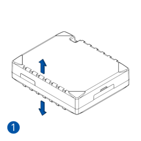
#Gently remove {{{model| | # Gently remove {{{model|FMM125}}} '''cover''' using '''plastic pry tool''' from both sides.<p><b>Note:</b> To properly open a new case please watch this [https://youtu.be/PBXVNXfRjg0 video].</p> | ||
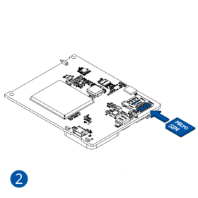
#Insert '''{{{sim_type|Micro-}}}SIM''' card as shown with '''PIN request disabled''' or read {{{ | # Insert '''{{{sim_type|Micro-}}}SIM''' card as shown with '''PIN request disabled''' or read '''[[{{{model|FMM125}}} Security info|Security info]]''' how to enter it later in [[Teltonika Configurator]]. Make sure that {{{sim_type|Micro-}}}SIM card '''cut-off corner''' is pointing forward to slot. {{{dual_sim|'''SIM slot 1''' is closer to PCB, '''SIM slot 2''' is the upper one.}}} | ||
# | {{{be_battery|# Connect '''battery''' as shown to device. Position the battery in place where it does not obstruct other components. | ||
# After '''configuration''', see “'''[[{{{model|FMM125}}}_First_Start#PC Connection (Windows)|PC Connection (Windows)]]'''”, attach device '''cover''' back.}}} | |||
[[Image:FMC13A_cover1_correct.png|280px]][[Image:FMC13A_cover2_correct.png|280px]][[Image:FMC13A_cover3_correct.png|280px]][[Image:FMC13A_cover4_correct.png|280px]] | [[Image:FMC13A_cover1_correct.png|280px]][[Image:FMC13A_cover2_correct.png|280px]][[Image:FMC13A_cover3_correct.png|280px]][[Image:FMC13A_cover4_correct.png|280px]] | ||
Revision as of 14:08, 23 May 2022
How to insert Micro-SIM card and connect the battery
- Gently remove FMM125 cover using plastic pry tool from both sides.
Note: To properly open a new case please watch this video.
- Insert Micro-SIM card as shown with PIN request disabled or read Security info how to enter it later in Teltonika Configurator. Make sure that Micro-SIM card cut-off corner is pointing forward to slot. SIM slot 1 is closer to PCB, SIM slot 2 is the upper one.
- Connect battery as shown to device. Position the battery in place where it does not obstruct other components.
- After configuration, see “PC Connection (Windows)”, attach device cover back.
 |
Micro-SIM card insertion/removal must be performed when device is powered off – external voltage and internal battery disconnected. Otherwise Micro-SIM card might be damaged or device will not detect it. |


