FMB641 CAN \ Tachograph
CAN \ Tachograph
CAN \ Tachograph are used to configure device when connection of CAN1 and CAN2 BUS lines are performed.
Teltonika recommendations:
- FMB641 CAN1 connected to vehicle's FMS(J1939) BUS line
- FMB641 CAN2 connected to vehicle's Tachograph - Instructions can be found on FMB640 and Tachograph Solution wiki page;
Tachograph Settings
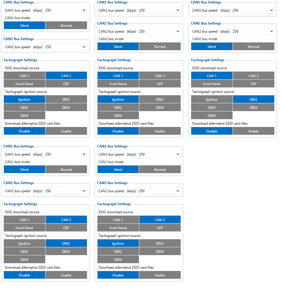
In FMB641 configurator “CAN/Tachograph” section tachograph settings should be set in order to download files.
DDD download source – to which CAN line tachograph is connected;
Tachograph ignition source – which DIN is connected to vehicle ignition ("Ignition" parameter - tachograph ignition source will be the same as configured in "System" -> "Ignition Source");
FMB641 can be wired to Tachograph using instructions provided in FMB640 and Tachograph Solution wiki page.
Alternative DDD download
Enables the possibility to download specific DDD driver and co-driver card data from non-original locations. It may include last download information.
NOTE: Alternative DDD download WILL NOT work with GEN2 Tachographs (VDO 4.0 or Stoneridge SE5000 8.0)
By default, this parameter is DISABLED.
WEB Tacho Settings
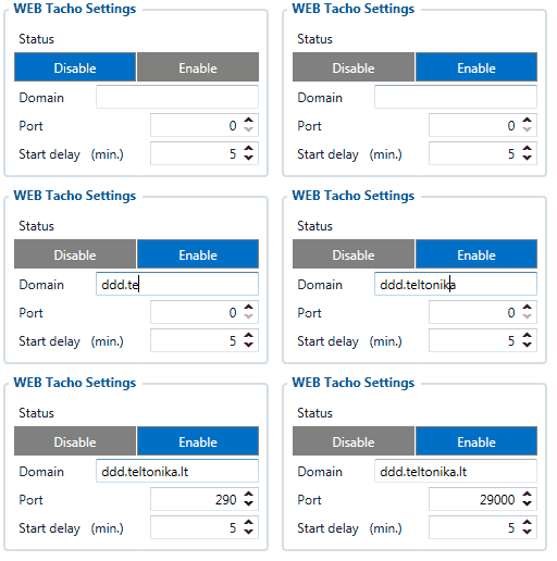
WEB Tacho Settings are used to configure Tacho WEB server to which device periodically connects.
WEB Tacho Settings:
Status - functionality enabling;
Domain – server domain where files will be send;
Port – server port where files will be send;
Start delay – delay after turning on ignition to start procedure of file sending.
FMS settings
FMS settings is used to configure FMS source.
If you have FMS wired to FMB641 CAN1, FMS source should be selected as CAN1.
If you have FMS wired to FMB641 CAN2, FMS source should be selected as CAN2.
CAN Termination resistor
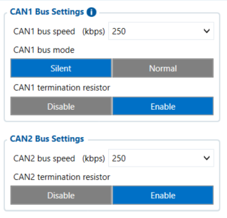
FMB641 has electronically controllable CAN termination resistor on CAN1 and CAN2 lines. This means that CAN line 120Ω resistance can be switched ON or OFF.
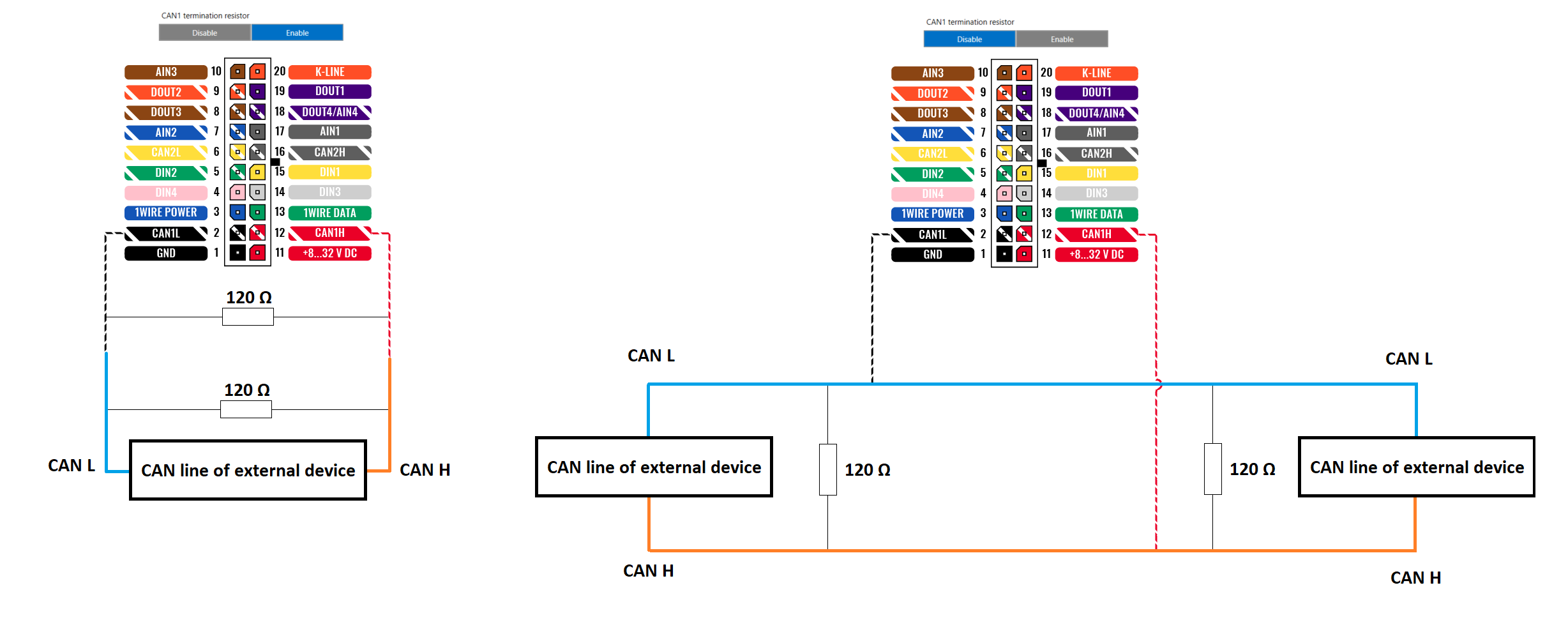
In most cases - devices in CAN communication lines have 120Ω between CAN LOW and CAN HIGH lines. When connecting two CAN devices in parallel - overall resistance becomes 60Ω which is suitable for correct CAN communication.
By default FMB641 CAN Termination resistor is enabled - therefore when connecting to only one external CAN device - overall resistance will be 60Ω.
If FMB641 has to be connected to CAN line where there already are 2 main devices with 120Ω resistance - CAN termination resistor has to be turned off . Then overall resistance of CAN line is left unchanged at 60Ω - therefore CAN communication is uninterrupted.


