Template:FMB Features settings
Eco/Green Driving
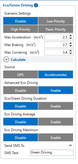
When vehicle parameters exceed the values of Max Acceleration, Max Braking or Max Cornering parameters, the scenario is activated: a record is generated. You can configure all three parameters in m/s2 units. The scenario is activated until the current Acceleration, Braking, or Cornering value decreases below the set parameter value.
Parameters used with Eco/Green Driving functionality are given in a table below.
| Parameter name | Description |
|---|---|
| Scenario Settings | Enable/Disable Green driving functionality |
| Max Acceleration | Value which can be reached while accelerating without triggering harsh acceleration event. |
| Max Braking Acceleration | Value which can be reached while braking without triggering harsh braking event. |
| Max Cornering Acceleration | Value which can be reached while cornering without triggering harsh cornering event. |
| Source | Which source (GPS or accelerometer) data will be collected from. |
| Advanced Eco Driving | When this parameter is enabled device uses an advanced Eco Driving algorithm and sends different IO (maximum, average) elements instead of IO to server. More details about this option is decribed below. |
| Eco/Green Driving Duration | If enabled, additional record with Eco/Green Driving event duration (ms) will be saved and send to server. When GPS is selected as the data source duration accuracy will be in seconds. |
| Output Control | Which FMB1YX Digital Output will be used for accesory (buzzer, LED and etc.) activation/deactivation. |
Advanced Eco Driving
From 03.25.14.Rev.03 base firmware version new parameter has been added (Eco Driving Maximum and Eco Driving Average) to FMT100 device. This parameter is enabled by default.
When this parameter is enabled device uses an advanced Eco Driving algorithm and sends different IO (maximum, average) elements instead of IO to server. When enabled, device does not send Green Driving value IO element 254.
| Parameter name | Description |
|---|---|
| Eco Driving Average | If Eco/Green driving is enabled and accelerometer is selected as the data source, enabling Eco Driving Average will cause records with Eco Driving event Average value to be saved and send to the server. |
| Eco Driving Maximum | If Eco/Green driving is enabled and accelerometer is selected as the data source, enabling Eco Driving Maximum will cause records with Eco Driving event Maximum value to be saved and send to the server. |
Data output
Data from accelerometer/GPS are continuously monitored and processed and are used to decide whether a harsh event has occurred. If either of three cases is satisfied, an event is generated and a record is saved and sent to the server (FMB1YX must be properly configured in order to send the record). Event value is multiplied by 100 before sending/saving records to get more precision when displaying data.
Auto calibration
The auto-calibration process is as follows:
- The vehicle is stopped.
- There is a straight road ahead.
- Send SMS "auto_calibrate:set" to the FMB device.
- Accelerate to >30 km/h for 5 sec.
- FMB will send a response when calibration is completed successfully.
Calibration is saved to internal flash memory, which means it will stay after a reset. To check auto-calibration status send a following short text message to the FMB device: "auto_calibrate:get".
Over Speeding
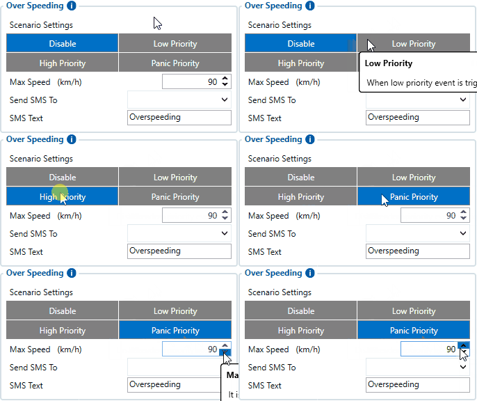
When vehicle speed exceeds configured maximum speed value the scenario is activated, and an event record is generated and digital output status is changed to 1 when configured.
Detected speed has to be greater than configured max speed +3% of configured max speed for the overspeeding event to start. To stop overspeeding event detected speed has to be lower than configured max speed -3% of configured max speed.
Configurable parameters:
- Scenario settings – defines the priority of overspeeding scenario: 0 – disabled, 1 – low, 2 – high, 3 – panic.
- Max speed – it is the maximum allowed speed that can be reached. If the speed exceeded configured value, then the event will occur.
- Send SMS to – the GSM number to which the SMS event will be sent.
- SMS text – SMS text.
Jamming
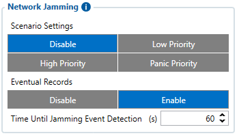
When a device detects GSM signal jamming, it activates the Jamming scenario. The device then starts a configurable timeout before responding that is intended to reduce false positives. After the timeout ends, the device generates an event record
Note that this scenario will not work with Deep Sleep, Ultra Deep Sleep and Online Deep Sleep modes, since they disable the device's GSM module to save power.
Eventual Records parameter can be configured: when it is disabled scenario status value will appear in each AVL record, otherwise, it will be appended only to eventual records.
For a more visual explanation, take a look at the video made by Teltonika explaining the use-case of Jamming Detection: Teltonika Jamming Detection scenario
GNSS Jamming
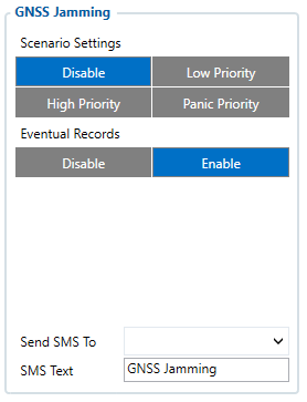
GNSS Jamming is the transmission of radio signals that disrupts communications between tracker and satellites by decreasing the signal to noise ratio. When a device detects GNSS signal jamming, it activates the GNSS Jamming scenario. The device then generates and sends a record to the server, depending on hardware model activates Digital Output and optionally sends SMS notification to configured GSM number. After device regains GNSS signal, Digital Output is immediately deactivated and a new record is sent to the server. This Digital Output activation can be used to trigger measures to disrupt potential thieves using GNSS signal jamming to steal your vehicle. GNSS Jamming record is stored in AVL ID 318 parameter and has 3 possible values:
- 0 - No Jamming,
- 1 - Jamming warning status, which means that signal and accuracy is disrupted but device is able to hold GPS fix for at least 5 seconds.
- 2 - Jamming critical status, which means that device is not able to acquire GPS fix.
Worth mentioning, that Jamming Detection can go from any state to any other in 1 second intervals. It is completely dependent on received NMEA data by GNSS receiver. Therefore, it is possible in repeated jamming scenario for the state to rapidly go from 0 to 2 and backwards. Also, GNSS Jamming functionality is capable to separate indoor areas (e.g. underground parking) from events when jamming is actually happening. This is possible because in-band jamming will affect internal PGA (Programmable Gain Amplifier) degrade, as a result, CNR (Carrier-to-noise ratio) will degrade as well. On the other hand, if CNR degrade is degraded only because of underground or signal covered, internal PGA gain will keep almost the same.
Eventual Records parameter can be configured: when it is disabled scenario status value will appear in each AVL record, otherwise, it will be appended only to eventual records.
Note: GNSS Jamming is only available since 03.28.03.Rev.03 or newer firmware version.
Note: GNSS Jamming is not available on 3.80, 3.82 but available on 5.10, 5.1.5, 5.1.8 or newer GNSS module firmware versions. GNSS module version can be checked by SMS\GPRS command - getver
Note that this scenario will not work with Deep Sleep, Ultra Deep Sleep and Online Deep Sleep modes, since they disable the device's GNSS module to save power.
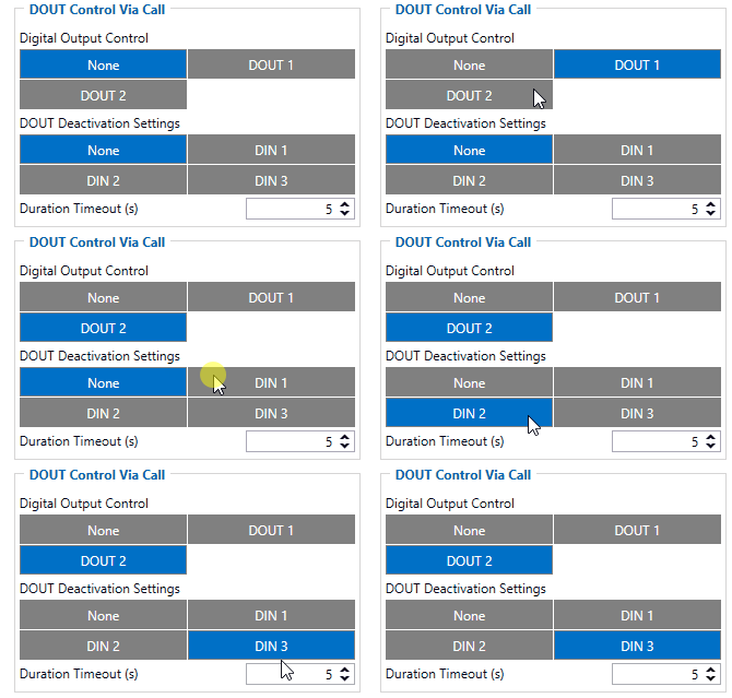
DOUT Control Via Call
The scenario is activated and digital output is ON when a call is received from a number that is on the authorized numbers list.
Call control functionality is the following:
- When FMB1YX is configured to control DOUT1/DOUT2 the device waits for an incoming call from a configured secure number. If a call is received FMB1YX turns on DOUT1/DOUT2 for a user defined Duration Timeout. If duration timeout set to "0" DOUT1/DOUT2 will be OFF.
- DOUT1/DOUT2 can be turned off by Duration Timeout or by digital input 1, digital input 2 or digital input 3.
- DOUT1/DOUT2 will always be ON if, for example, DOUT deactivation is set to DIN1, but DIN1 will be never turned ON, or when duration timeout is set to the maximum value (2147483647) which is about 68 years.
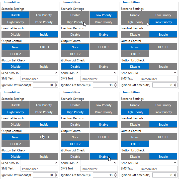
Immobilizer
If DOUT Control is disabled, the scenario will only generate events without digital output activation. If DOUT Control is enabled DOUT1/DOUT2 turns ON if ignition turns ON (Ignition Source is configured to 1). After any iButton ID (or RFID card) is attached, DOUT1/DOUT2 turns OFF. After iButton identification configured Ignition Source can be turned OFF (Ignition Source is configured to 0) for no longer than 30 seconds, otherwise, the immobilizer must be repeated. If the iButton List Check parameter is enabled, the authorization will be successful only if the attached iButton is specified in the iButton list.
The ignition off timeout parameter is used to set the duration after which authorization is activated when the ignition is turned off. For example, if the Ignition off timeout is set to 30 seconds when the driver turns the ignition off, he has 30 seconds until the immobilizer security check turns on again. In other words, if the driver turns off the ignition and turns it back on in less than 30 seconds, then he will not have to attach the iButton to the reader again.
From the firmware version 03.25.14 iBeacon authentication was introduced. iBeacon authentication works in the same way as iButton authentication. To use authorized iBeacons, the iBeacon list should be filled in the device configurator. Instructions how to list iBeacons in FMB devices can be found here.
By using iBeacon authorization, the immobilizer feature can be used with devices that don't have a 1-wire data connection available.
iButton Read Notification
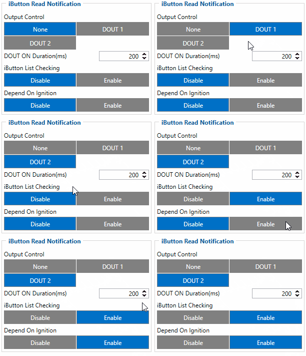
Output control parameter lets the user choose which DOUT will iButton blink. After connecting iButton, DOUT will blink for a period of time, which is configured in DOUT ON Duration parameter. The iButton List checking parameter configures whether the device reads the iButton ID from iButton list or not. For example if configured as Enabled, device will not blink DOUT unless the iButton is in the iButton list. If Depend on Ignition parameter is enabled, then Output will be triggered only if ignition is off (in addition to being in a list if iButton List Checking is also enabled). Output control examples when iButton is detected (if None is selected in Output Control – all of the following steps will be skipped):
- If both iButton List Checking and Depend on Ignition are disabled – Output is triggered.
- If iButton List Checking is enabled and Depend on Ignition is disabled – Output is triggered only if iButton is in the list.
- If iButton List Checking is disabled but Depend on Ignition is enabled – Output is triggered only if ignition is off.
- If both iButton List Checking and Depend on Ignition are enabled – Output will trigger if iButton is in the list and ignition is off.
iButton Read Notification parameters:
- Output control – available scenario settings for module Digital output activation/deactivation
- DOUT ON duration – a value in seconds, for how long DOUT1/DOUT2 should be active.
- iButton List checking - parameter configures that device reads the iButton ID from list or not.
- Depend on Ignition - Output will be triggered only if ignition is off
GNSS Fuel Counter
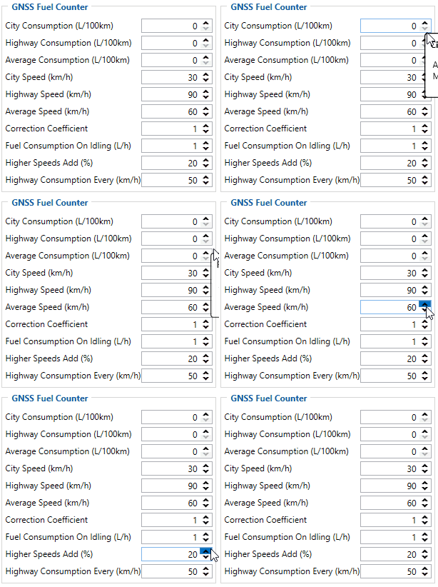
To configure Fuel Counter parameters use fuel consumption norms which are presented in the technical documentation of the vehicle. By default speeds for these fuel consumption norms are: City – 30 km/h, Average - 60 km/h, Highway - 90 km/h. These values can be changed.
When speed is higher than the highway fuel consumption speed, x% of highway fuel consumption is added every extra y km/h, by default FMB1YX adds 20% every 50 km/h of extra speed. For example, the fuel consumption is (1.2 * (Highway Fuel Consumption)) at 140 km/h and (1.4 * (Highway Fuel Consumption)) at 190 km/h.
Correction coefficient is used to correct every value of fuel consumption which is sent to the server through an expression of ((Used Fuel) * Correction coefficient). By default, it is 1, with minimum and maximum values of accordingly 0.01 and 2. For example, when the correction coefficient is 1 and FMB1YX calculates that the amount of used fuel over 35 m distance is 20 ml, the value of 20 ml will be sent to the server, and if correction coefficient is 1.2, the value of 20 * 1.2 = 24 ml will be sent to the server.
Fuel Consumption on Idling is used to calculate fuel consumption when the ignition is on, but the vehicle is stationary. The consumption value is 1 l/h by default, with a minimum and maximum of accordingly 0 and 5 l/h. This parameter is less than 1.0 l/h for almost all diesel cars and is equal to about 1.5 – 2.0 l/h for gasoline cars.
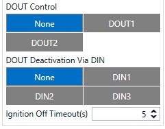
DOUT Control Via Ignition
This feature allows direct control of DOUT by configured ignition source status. When enabled, the function will start to monitor ignition status, and once the ignition changes state from On to Off after configured Ignition Off a timeout, selected DOUT (Digital Output) will be turned On.
Turning DOUT Off is possible with enough voltage applied to the configured DIN (Digital Input) or by turning on the ignition. Voltage requirements: DIN1 – 7.5V, DIN2-4 – 2.5V.
| Parameter name | Description |
|---|---|
| DOUT Control | Scenario controls configured DOUT if ignition timeout exceeds its limit |
| DOUT Deactivation Via DIN | DOUT is turned off if configured DIN is in on (voltage applied) state |
| Ignition Off timeout | Duration (in seconds) after which DOUT is turned on, when ignition is turned off |
Ignition ON Counter
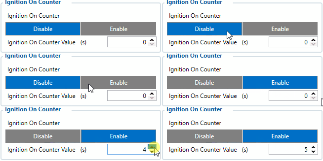
Ignition ON Counter scenario counts the time spent with the ignition in the resolution of seconds.
It is possible to configure a starting value of the counter. Maximum value: 2147483647 seconds or 596523.235 hours
NOTE THAT, when entering a starting value, the value must be in seconds!
Example of Ignition On Counter I/O element:
DOUT 1 Output Type
DOUT 1 Output Type functionality sets the initial DOUT1 state. If functionality is configured in Normal mode digital output inactive state is low and when it is controlled by any scenario digital output is set to high state. Whenever functionality is configured in Inverted mode digital output inactive state is high and when it is controlled by any scenario digital output is set to low state.
DOUT1 in Normal state:
DOUT1 in Inverted state:
- Notice! Digital output type control functionality will not affect SMS/GPRS command setdigout execution.
![]() Available from Firmware version: 03.27.07.Rev.00
Available from Firmware version: 03.27.07.Rev.00
