FISHING BOATS TRACKING WITH IP67 RATING GPS DEVICES
Solution description
Global seafood consumption has more than doubled in the last 50 years, along with overfishing, bottom trawling, the use of explosives, and a wide range of illegal and/or unauthorised fishing. Surely, preserving aquaculture for current and future generations is essential. This has led to the introduction of many fishing restrictions and regulations worldwide but they must be monitored, and Teltonika Telematics can help with that.
We glad that you decide to test our “Fleet Maintenance Schedules (Delivery)” solution. Here you will find how to prepare and to test this solution.
What you need for a solution?
- Teltonika FM device which is compatible with this use case. Recommended devices: FMB225, FMB230, FMB240, FMC225, FMC230, FMM230, FMB965, FMB202, FMB204.
- The SIM card in order to get data to your server.
- FOTA to remotely send the configuration to the device.
- Teltonika Configurator to set up FM device correctly for the solution.
Installation
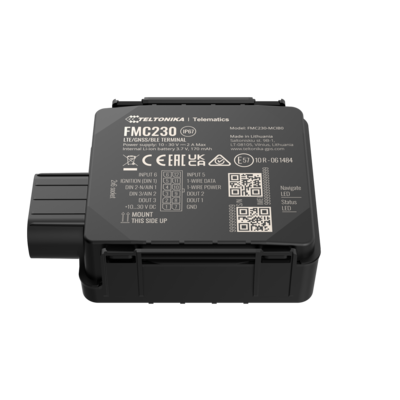
FMC230 device should be mounted with the device logo view to the open sky for the best device performance with not less than ¾ of metal free area. FMC230 has IP67 protection class. Top performance is reached if mounted outside the boat on the cover. The device has adhesive tape to securely place the device. SIM card should be inserted in the module while the connector is plugged off (while module has no power).

Configuration
Prerequisites:
Read through First start guide
Understanding of possible Sleep modes.
Configuring Fleet Maintenance Schedules:
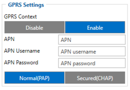
Parameter ID – Parameter name GPRS settings:
- 2001 – APN
- 2002 – APN username (if there are no APN username, empty field should be left)
- 2003 – APN password (if there are no APN password, empty field should be left)
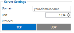
Server settings:
- 2004 – Domain
- 2005 – Port
- 2006 – Data sending protocol (0 – TCP, 1 – UDP)
After successful GPRS/SERVER settings configuration, FMC230 device will synchronize time and update records to the configured server. Time intervals and default I/O elements can be changed by using Teltonika Configurator or SMS parameters.
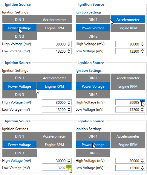
Possible ignition sources:
DIN 1 (Digital Input 1) - if DIN1 is 1 - ignition is ON; if DIN1 value is 0 - ignition is OFF;
Power Voltage - if voltage is between High Voltage Level and Low Voltage Level (below Ignition Settings options) - ignition is ON; if voltage is higher than High Voltage Level or lower than Low Voltage Level - ignition is OFF.
Engine RPM - if RPM from OBD II or CAN is higher than 0 - ignition is ON; if RPM from OBD II or CAN is equal to 0 - ignition is OFF;
Accelerometer - if movement sensor detects movement - ignition is ON; if movement is not detected - ignition is OFF;
More than one ignition source can be selected at the same moment. When there are 2 or more sources selected, at least one condition has to be met to change Ignition status.
DIN 3 (Digital Input 3) - if DIN3 is 1 - ignition is ON; if DIN3 value is 0 - ignition is OFF;
Example: DIN1 and Accelerometer are selected as the Ignition source. When the device detects movement, Ignition status will change to 1, regardless that DIN1 value is 0. Users can select movement start and movement stop delay time - those parameters are used when the accelerometer is selected as an ignition source. Ignition status is used in power management and the following functionalities: Eco/Green Driving, Excessive Idling, Fuel Consumption, Over Speeding, Towing Detection and Trip.
Parameter ID - Parameter name
Ignition source settings:
- 101 - Ignition Source (1 - DIN1, 2 - Accelerometer, 3 - Power Voltage, 4 - Engine RPM, 5 - DIN3).
104 - Hight Voltage ( MIN - 0, MAX - 30000).
105 - Low Voltage ( MIN - 0, MAX - 29999).
Static navigation settings:
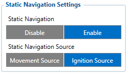
- 106 - Static navigation (0 - Disable, 1 - Enable).
- 112 - Static navigation source (1 - Movement, 2 - Ignition, 3 - Movement and Ignition).
Jamming settings:
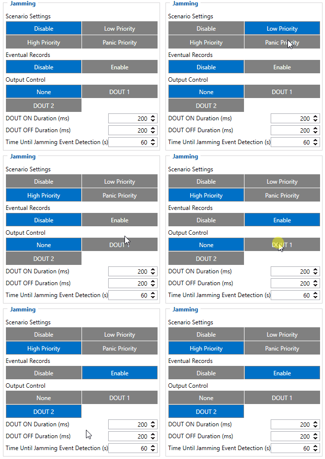
- 11300 - Scenario settings (0 - Disable, 1 - Low priority, 2 - High priority, 3 - Panic priority).
- 11303 - Eventual records (0 - Disable, 1 - Enable).
- 11304 - Output control (0 - None, 1 - DOUT1, 2 - DOUT2).
- 11305 - Timeout (Seconds "0 - 65535").
Unplug settings:
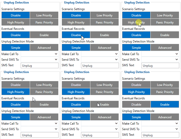
- 11500 - Scenario settings (0 - Disable, 1 - Low priority, 2 - High priority, 3 - Panic priority).
- 11501 - Eventual records (0 - Disable, 1 - Enable).
- 11502 - Detection mode (0 - Simple, 1 - Advanced).
- 7036 - Send SMS to (Phone number).
- 8036 - Sms text (Text).
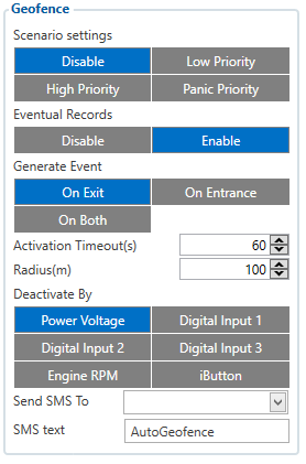
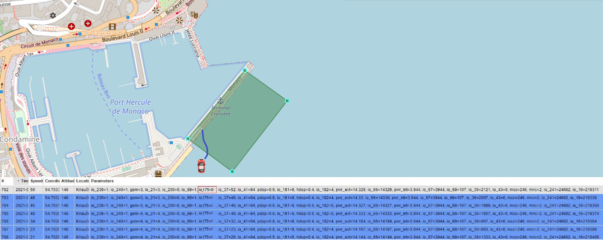
AutoGeofencing settings:
- 20000 - Priority (0 - Disable, 1 - Low priority, 2 - High priority, 3 - Panic priority).
- 20002 - Eventual records (0 - Disable, 1 - Enable).
- 20003 - Activation timeout (Seconds "0 - 65535").
- 20001 - AutoGeofence event generating (0 - On exiting zone, 1 - On entering zone, 2 - On both).
- 20005 - Deactivate by (0 - Power voltage, 1 - Digital input 1, 2 - Engine RPM, 3 - Digital input 2, 4 - Digital input 3, 5 - iButton).
- 20004 - Radius (Value "5-1000000").
- 7030 - Send SMS to (Phone number).
- 8030 - Sms text (Text).
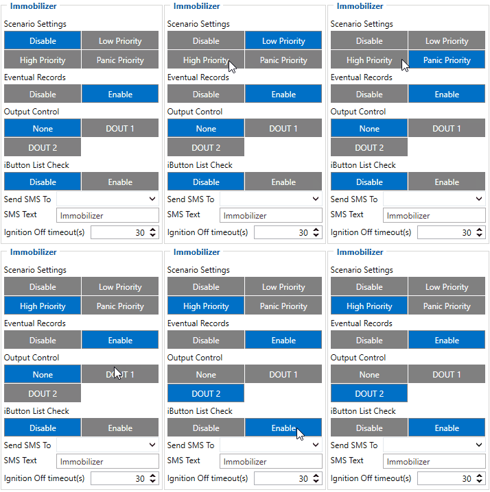
Immobilizer settings:
- 11700 - Scenario settings (0 - Disable, 1 - Low priority, 2 - High priority, 3 - Panic priority).
- 11701 - Eventual records (0 - Disable, 1 - Enable).
- 11702 - Output control (0 - Disable, 1 - Enable (DOUT 1), 2 - Enable (DOUT 2)).
- 11703 - iButton list check (0 - Disable, 1 - Enable).
- 60068 - Ignition Off timeout (Seconds "0 - 65535").
- 60076 - Alcotester Check (0 - Disable, 1 - Enable).
- 60077 - BAC Threshold (‰ - percents).
- 60076 - Blood Alcohol Content Event (0 - Disable, 1 - Enable).
- 7140 - Send SMS to (Phone number).
- 8140 - Sms text (Text).
Quick start: From default configuration to Fleet Maintenance Schedules in one SMS:
" setparam 101:1;106:1;112:2;11300:2;11303:1;11304:2;11305:10;11500:3;11501:1;11502:1;7036:Telephone Number;8036:SMS Text;20000:3;20002:1;20003:60;20001:0;20005:1;20004:100;7030:Telephone Number;8030:SMS Text;11700:2;11701:1;11702:1;11703:1;60068:10;
Note: Before SMS text, two space symbols should be inserted if no SMS username or password was set in SMS \ Call settings.
Parsing information
Prerequisites:
Open TCP/UDP port
Go to Java parser first start guide
Parsing example:
| Unparsed received data in hexadecimal stream |
|---|
| 00000000000004d608130000017738b113a8000efcea74209c63c200b60096050010000c05ef01f0011505AF00
450105b50008b600074230fB6c430f3d44006b02f10000601a1000038753000 000017738b124 209c63d05b50008b600074230 ff430f3d44006b020000601a100003875300002900017738b11f600001f0011505 |
| AVL Data Packet Part | HEX Code Part |
|---|---|
| Zero Bytes | 00 00 00 00 |
| Data Field Length | 00 00 04 d6 |
| Codec ID | 08 (Codec 8) |
| Number of Data 1 (Number of Total Records) | 13 |
| Timestamp | 00 00 01 77 38 b1 13 a8 (Mon Jan 25 08:37:46 UTC 2021) |
| Priority | 00 |
| Longitude | 00 01 77 38 |
| Latitude | b1 13 a8 00 |
| Altitude | 0e fc |
| Angle | ea 74 |
| Satellites | 20 |
| Speed | 9c 63 |
| N of Total ID | 9 |
| N1 of One Byte IO | 05 |
| 1’st IO ID | EF (AVL ID: 239, Name: Ignition) |
| 1’st IO Value | 01 |
| 2’nd IO ID | F0 (AVL ID: 240, Name: Movement) |
| 2’nd IO Value | 01 |
| 3’rd IO ID | 15 (AVL ID: 21, Name: GSM Signal) |
| 3’rd IO Value | 05 |
| 4'th IO ID | AF (AVL ID: 175, Name: Auto Geofence) |
| 4'th IO Value | 00 |
| 5'th IO ID | 45 (AVL ID: 69, Name: GNSS Status) |
| 5'th IO Value | 01 |
| N2 of Two Byte IO | 03 |
| 1’st IO ID | B5 (AVL ID: 181, Name: GNSS PDOP) |
| 1’st IO Value | 8 |
| 2’rd IO ID | 42 (AVL ID: 66, Name: External Voltage) |
| 2’rd IO Value | 30 FC |
| 3'th IO ID | 43 (AVL ID: 67,Name: Battery Voltage) |
| 3'th IO Value | 0F 3D |
| N4 of Four Byte IO | 01 |
| 1’nd IO ID | (AVL ID: 16, Name: Total Odometer) |
| 1’nd IO Value | 03 87 53 |
| CRC-16 | 00 00 73 2E |
Demonstration in platform
WIALON: Open WIALON → open messages → push unit ( select your device) → choose the date from which to which to show the records → select message (data messages) → push execute button and you will see all information.
