From Teltonika Telematics Wiki
(
diff)
← Older revision | Approved revision (diff) | Latest revision (diff) | Newer revision → (diff)

|
Please order accessories separately as they are not included into device package.
|
| Accessory and its description
|
Accessory connection schematic
|
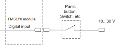
| Alarm buttons, door sensors etc.
|
Panic button connection to FMB9YX
|
| Alarm buttons, door sensors, ignition, etc. have two output states: high or low. FMB9YX Digital inputs are used to detect these states.
|
|
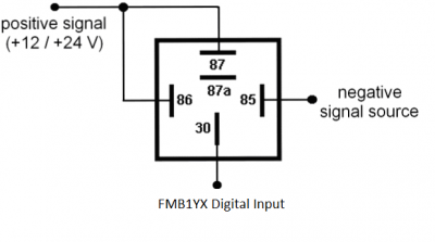
| Relays
|
Inverting relay connection to FMB9YX
|
| In cases when sensor output signal is negative, an additional relay has to be installed to convert negative signal to positive.
|
|
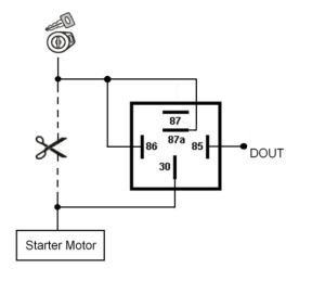
| Immobilizer relay
|
Immobilizer relay connection to FMB9YX output
|
| When connected as shown on the right hand side, FMB9YX disables engine starter when output is ON.
|
|
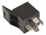
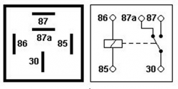
| Automotive relay
|
Automotive relay pinout
|
An ordinary automotive relay is used to invert input signal or to immobilize engine starter. Note that relays can be 12 V or 24 V capable.
|
|


