FMA120 General description
Main Page > EOL Products > FMA120 > FMA120 Manual > FMA120 General description
FMA120 is a tracking terminal with GNSS and GSM connectivity, which is able to collect device coordinates and transfer them via GSM network to a server. This device is perfectly suitable for applications, which require the location acquirement of remote objects.
Package contents
The FMA120 device is supplied to the customer in a cardboard box containing all the equipment that is necessary for operation. The package contains:
- FMA120 device;
- Input and output power supply cable with 2x5 connection pins;
- Micro USB cable;
Basic characteristics
GSM / GPRS features:
- Quad band supported (GSM 850 / 900 / 1800 / 1900 MHz);
- GPRS Multi-Slot Class 12(up to 240 kbps);
- GPRS Mobile Station Class B;
- SMS (text, data).
GNSS features:
- Tracking: 33/ 99 acquisition channels;
- Up to -165 dBm sensitivity;
- Hot start < 1s;
- Warm start < 25s;
- Cold start < 35s;
- NMEA -183 protocol;
- GPS, GLONASS, GALILEO, BEIDOU, SBAS, QZSS, DGPS, AGPS;
- Accuracy < 3m.
Hardware features:
- Cortex®-M3 processor;
- 1 MB internal Flash memory;
- Built-in accelerometer.
Interface features:
- Power supply: 10 ÷ 30V;
- USB port;
- 3 digital inputs;
- 1 analog input;
- 2 open collector digital outputs;
- 1Wire® temperature sensor
- 1Wire® iButton
- LEDs indicating device status.
Special features:
- Any element event triggers (external sensor, input, speed, temperature, etc.);
- Highly configurable data acquisition and sending;
- Multiple Geo-fence areas;
- Sleep mode;
- Deep sleep mode;
- Configurable scenarios available;
- Real-time process monitoring;
- Authorized number list for remote access;
- Firmware update over GPRS or USB port;
- Configuration update over GPRS, SMS or USB port;
- TCP/IP or UDP/IP protocol support;
- 3500 record storing.
Technical features
| Part name | Physical specification |
|---|---|
| Navigation indication | LED |
| Modem indication | LED |
| Socket | Soldered inner socket |
| USB | Micro USB socket |
| GNSS | Internal GNSS antenna |
| GSM | Internal GSM antenna |
| Technical details | |
|---|---|
| 2 W max. Current consumption at 12 V |
GPRS: average 69.15 mA rms Nominal: average 35.23 mA rms GNSS sleep: average 19.72 mA Deep Sleep: average 7.35 mA Online Deep Sleep: average 10.96 mA Ultra Deep Sleep: average 5.69 mA |
| Battery charge current | Average 140 mA |
| Operating temperature | -25..+55 °C |
| Storage temperature | -40..+70 °C |
| Storage relative humidity | 5..95% (no condensation) |
| Device + case + battery weight | 55 g |
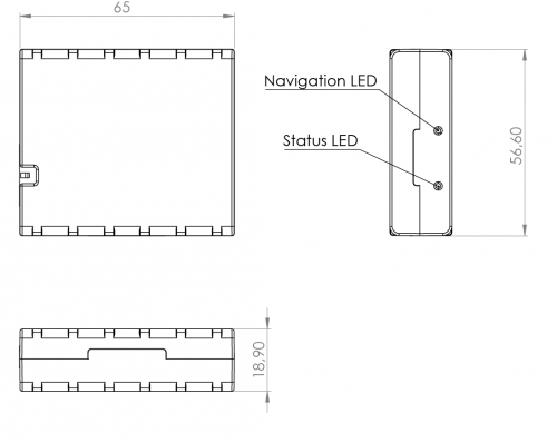
Dimension drawing:

Technical information about internal battery
| Internal back-up battery | Battery voltage (V) | Nominal Capacity (mAh) | Power (Wh) | Charge temperature (°C) | Discharge temperature (°C) | Storage temperature (°C) |
|---|---|---|---|---|---|---|
| Li-ion rechargeable battery | 3.75~3.90 | 170 | 0.64 – 0.66 | 0 to +45 | -20 to +60 | -20 to +45 for 1 month -20 to +35 for 6 months |
Batteries are covered by 6 month warranty support.
| CAUTION: RISK OF EXPLOSION IF BATTERY IS REPLACED BY AN INCORRECT TYPE. DISPOSE OF USED BATTERIES ACCORDING TO THE INSTRUCTIONS. | |
 |
Battery should not be disposed of into general household waste. Bring damaged or worn-out batteries to your local recycling center or dispose them into a battery recycle bin commonly found in supermarkets. |
Electrical characteristics
| Characteristic description | Value | |||
|---|---|---|---|---|
| Min. | Typ. | Max. | Unit | |
| Supply Voltage: | ||||
| Supply Voltage (Recommended Operating Conditions) |
+10 | +30 | V | |
| Digital Output (Open Drain grade): | ||||
| Drain current (Digital Output OFF) | 120 | µA | ||
| Drain current (Digital Output ON, Recommended Operating Conditions) |
0.1 | 0.5 | A | |
| Static Drain-Source resistance (Digital Output ON) |
400 | 600 | mΩ | |
| Digital Input: | ||||
| Input resistance (DIN1) | 47 | kΩ | ||
| Input resistance (DIN2) | 51.7 | kΩ | ||
| Input resistance (DIN3) | 47 | kΩ | ||
| Input voltage (Recommended Operating Conditions) |
0 | Supply voltage | V | |
| Input Voltage threshold (DIN1) | 7.5 | V | ||
| Input Voltage threshold (DIN2) | 2.5 | V | ||
| Input Voltage threshold (DIN3) | 2.5 | V | ||
| Analog Input: | ||||
| Input voltage (Recommended Operating Conditions), Range 1 |
0 | +10 | V | |
| Input resistance, Range 1 | 150 | kΩ | ||
| Measurement error on 12V, Range 1 | 3 | % | ||
| Additional error on 12 V, Range 1 | 360 | mV | ||
| Measurement error on 30 V, Range 1 | 3 | % | ||
| Additional error on 30 V, Range 1 | 900 | mV | ||
| Input Voltage (Recommended Operating Conditions), Range 2 |
0 | +30 | V | |
| Input resistance, Range 2 | 150 | kΩ | ||
| Measurement error on 12V, Range 2 | 3 | % | ||
| Additional error on 12 V, Range 2 | 360 | mV | ||
| Measurement error on 30 V, Range 2 | 3 | % | ||
| Additional error on 30 V, Range 2 | 900 | mV | ||
| Output Supply Voltage 1-Wire: | ||||
| Supply voltage | +4.5 | +4.7 | V | |
| Output inner resistance | 7 | Ω | ||
| Output current (Uout > 3.0 V) | 30 | mA | ||
| Short circuit current (Uout = 0) | 75 | mA | ||
| Ground sense: | ||||
| Input resistance | 38.45 | kΩ | ||
| Input voltage (Recommended operating conditions) |
0 | Supply voltage | V | |
| Input voltage threshold | 0.5 | V | ||
| Sink current | 180 | nA | ||
| CAN interface: | ||||
| Internal terminal resistor CAN bus (no internal termination resistor) |
- | - | - | Ω |
| Differential input resistance | 19 | 30 | 52 | kΩ |
| Recessive output voltage | 2 | 2.5 | 3 | V |
| Differential receiver threshold Voltage | 0.5 | 0.7 | 0.9 | V |
| Common mode input voltage | -30 | - | 30 | V |
 |
Analog Input error margin can increase if temperature varies. |
Absolute maximum ratings
| Characteristic description | Value | |||
|---|---|---|---|---|
| Min. | Typ. | Max. | Unit | |
| Supply Voltage (Absolute Maximum Ratings) |
-32 | +32 | V | |
| Drain-Source clamp threshold voltage (Absolute Maximum Ratings), (Idrain = 2 mA) |
+36 | V | ||
| Digital Input Voltage (Absolute Maximum Ratings) |
-32 | +32 | V | |
| Analog Input Voltage (Absolute Maximum Ratings) |
-32 | +32 | V | |