DualCam Data Sending Parameters ID
DualCam RS232 camera support
DualCam camera support was introduced from firmware version 03.27.06.Rev.360. A new RS232 mode "DualCam" was added with parameters for setting control. The details of the RS232 mode parameter are provided in the table below.
| Parameter name | Parameter ID | Parameter value |
|---|---|---|
| RS232 Mode | 151 | 18 |

Configuration version 8.14.1.0 has to be used if configuration is being made in offline mode.
Camera Feature Settings Parameters ID

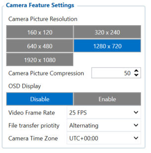
Once this mode is enabled, new tab “Camera Settings” appears on the left sidebar. This will contain the main parameters for configuring the camera settings The parameter IDs and values are provided in the table below. Once configuration is
saved to device, these parameters are updated.
| Parameter name | Parameter ID | Parameter values | Default values |
|---|---|---|---|
| Camera Picture Resolution | 66000 | ||
| 0 - 160 x 120 | 3 | ||
| 1 - 320 x 240 | |||
| 2 - 640 x 480 | |||
| 3 - 1280 x 720 | |||
| 4 - 1920 x 1080 | |||
| Camera Picture Compression | 66001 | [0 - 100] (%) | 50 |
| OSD Display | 66002 | 0 - Disabled | 0 |
| 1 - Enabled | |||
| Video Frame Rate | 66003 | 20, 25 and 30 (frames per second) | 30 |
OSD display - On Screen Display feature displays date and time in the upper left corner of the photo. This feature can be enabled or disabled.
Camera Scenario Settings Parameters ID

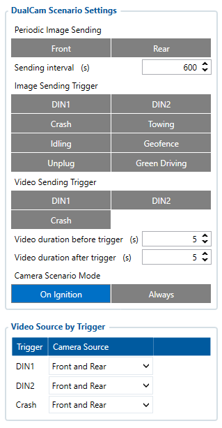
"Camera settings" tab also contains scenario settings that trigger camera video/photo capture when specific condition is met.
| Parameter name | Parameter ID | Parameter values | Default values |
|---|---|---|---|
| Periodic Image sending | 66006 | 0 - Disabled | 0 |
| 1 - Front Camera | |||
| 2 - Rear Camera | |||
| 3 - Both Cameras | |||
| Sending interval | 66007 | [10-1800] (seconds) | 600 |
| Image Sending Trigger | 66022 | ||
| 0 - None | 0 | ||
| 2 - DIN1 | |||
| 4 - DIN2 | |||
| 8 - Crash | |||
| 16 - Towing | |||
| 32 - Idling | |||
| 64 - Geofence | |||
| 128 - Unplug | |||
| 256 - Green Driving | |||
| Video sending trigger | 66023 | ||
| 0 - None | 0 | ||
| 2 - DIN1 | |||
| 4 - DIN2 | |||
| 8 - Crash | |||
| Video duration before trigger | 66009 | [1-10] (seconds) | 5 |
| Video duration after trigger | 66010 | [1-10] (seconds) | 5 |
| Camera Scenario Mode | 66020 | ||
| 0 - On Ignition | 0 | ||
| 1 - Always | |||
| Video source for trigger DIN1 | 66040 | ||
| 0 - None | 0 | ||
| 1 - Front | |||
| 2 - Rear | |||
| 3 - Front and Rear | |||
| Video source for trigger DIN2 | 66041 | ||
| 0 - None | 0 | ||
| 1 - Front | |||
| 2 - Rear | |||
| 3 - Front and Rear | |||
| Video source for trigger Crash | 66042 | ||
| 0 - None | 0 | ||
| 1 - Front | |||
| 2 - Rear | |||
| 3 - Front and Rear |
Video sending by trigger parameters ID
Video sending by trigger camera scenario monitors the selected trigger (video sending trigger parameter) and captures video from front, rear or both cameras before and after the event (video duration before trigger and video duration after trigger parameters). If the previously captured video has not finished downloading, then a new video capture is skipped until the old one has been sent. When this scenario is triggered, high priority eventual record is generated with the value corresponding to what triggered the scenario. See the table below.
| Parameter name | Parameter AVL ID | Parameter value |
|---|---|---|
| SOS trigger | 499 | 0 - Server request |
| 1 - DIN1 | ||
| 2 - DIN2 | ||
| 3 - Crash |
Image sending trigger parameters ID
Added Image sending trigger option (works the same way as Video sending trigger just triggers image sending). Both front and rear images will be sent.
For selecting multiple options using SMS/GPRS commands, add values of every option and set that value for this parameter.
For example, to set DIN1 (2), Crash (8), and Unplug (128) scenarios as triggers, add their values (2 + 4 + 128 = 138) and set the sum as the parameter value
| Parameter name | Parameter AVL ID | Parameter value |
|---|---|---|
| SOS trigger | 499 | 0 - Server request |
| 1 - DIN1 | ||
| 2 - DIN2 | ||
| 3 - Crash | ||
| 4 - Towing | ||
| 5 - Idling | ||
| 6 - Geofence | ||
| 7 - Unplug | ||
| 8 - Green Driving |
Camera ping transmission and TF status checking parameters ID
Camera pinging was implemented to periodically check if a camera is connected to a device. This is done via “Get TF status” command for both front and rear camera every 20 seconds when ignition is on. The received result from this command is stored in two corresponding AVL elements “Front camera state” and “Rear camera state”. The following do not only store TF status, but also if response from the camera was received or not.
| Parameter name | Parameter AVL ID | Parameter values |
|---|---|---|
| Front camera state: | 498 | 0 - Camera not detected |
| 1 - No card | ||
| Rear camera state: | 497 | |
| 2 - Card mount failed | ||
| 3 - Card mounted | ||
| 4 - Card faulty |
