TFT100 UART settings
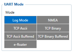
Mode
 Enables or disables UART functionality. |
UART Mode

Log Mode- UART prints TFT100 device log and does not respond to commands (Transmit mode).NMEA- UART prints GNSS NMEA log and does not respond to commands (Transmit mode).TCP ASCII/Binary- In TCP ASCII/Binary mode all data received from external device is sent directly to server. Data is encapsulated in codec 12 format. TCP Binary Mode has a delay of 30 ms, if no data is received for 30 ms, data is sent to the server. TCP ASCII mode waits for the End of Line (EOL) character (0x0D0A, \r\n) to pack data and send it to the server.TCP ASCII/Binary Buffered- TCP ASCII Buffered and TCP Binary Buffered modes are used to collect data from UART and save it in buffer if there is no link with server and data cannot be sent immediately. When link is established and there is data to transmit, then RS232 data from buffer is transmitted after all records are sent. Data is sent in codec 13 protocol.
Note! That in TCP ASCII and TCP Binary modes device sends data from external device only to main server. In Buffered modes – to both main and backup/duplicate servers.e-floater- e-floatero mode is used by e-floater e-scooters. When this mode is selected user will be able to read e-floater e-scooter specific data via UART.
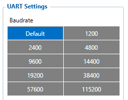
UART Baudrate
 UART Baudrate selection. |
UART Parity
 Parity selection. |
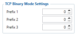
TCP Binary Mode settings

TCP Binary has a setting Prefix. It is possible to set Prefix 1, Prefix 2 or Prefix 3. These prefixes can be used separately or in unison. To configure this setting a value from 0 to 255 in decimal has to be entered. Device will convert this value to HEX and compare the 1st, 2nd or 3rd byte from incoming data. If the values do not match, device will not accept incoming data.
Example:
Incoming packet through RS485 using TCP Binary/Binary Buffered mode - 50 72 65 66 69 78 20 57 6f 72 6b 69 6e 67
- If Prefix 1 is set to 80 in decimal, it is equal to 50 in HEX. TFT100 device will then check the 1st byte of incoming data and compare to the set Prefix 1.
- If Prefix 2 is set to 114 in decimal, it is equal to 72 in HEX. TFT100 device will then check the 2nd byte of incoming data and compare to the set Prefix 2.
- If Prefix 3 is set to 101 in decimal, it is equal to 65 in HEX. TFT100 device will then check the 3rd byte of incoming data and compare to the set Prefix 3.
When values match, data will be accepted and saved to Buffer (using TCP Binary Buffered mode) or sent to server (using TCP Binary mode).
Incoming packet through RS485 using TCP Binary/Binary Buffered mode - 50 0 65 66 69 78 20 57 6f 72 6b 69 6e 67
- If Prefix 1 is set to 80 in decimal, it is equal to 50 in HEX. TFT100 device will then check the 1st byte of incoming data and compare to the set Prefix 1.
- If Prefix 2 is set to 114 in decimal, it is equal to 72 in HEX. TFT100 device will then check the 2nd byte 0 of incoming data and compare to the set Prefix 2.
Since Prefix 2 does not match incoming 2nd byte, data will not be accepted.

