TAT141 System settings
System Settings
PDOP filter
User can choose to enable or disable the PDOP filter. This feature allows to discard GNSS module output data if PDOP (Position Dilution of Precision) value is above selected threshold.
- PDOP filter threshold - PDOP filter threshold value can be entered from which the parameters will be filtered.
Input/Output Mode
User can choose specific external pins to work as an input or as output. Possible valid input/output configurations:
- Digital input 3 and Digital input 4 (value:5),
- Digital output 1 and Digital input 4 (value:6),
- Digital input 3 and Digital output 2 (value:9),
- Digital output 1 and Digital output 2 (value:10).
Analog Input Value Range
User can choose analog input range of 15 V or 150 V.
Input range used to determine lowest voltage for DIN1 and DIN2 activation.
Lowest voltage to enabled DIN for 15V range - 2.5V
Lowest voltage to enabled DIN for 150V range - 9V
DOUT Overcurrent protection
DOUTs have overcurrent protection that triggers after the current exceeds 300 mA. This protection works by generating pulses on the hardware. When the firmware detects at least 20 impulses on a DOUT it turns off that DOUT for 5 minutes. During this time all scenarios that try to turn this DOUT on will fail.
Data Protocol
User can choose which protocol version to use for data sending to server.
- Codec 8 supports up to 255 AVL ID;
- Codec 8 Extended supports up and above 255 AVL ID.
Location Settings
GNSS Source settings
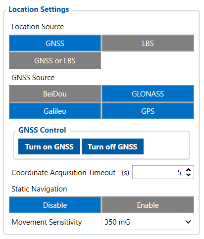
User can configure which GNSS system(s) to use.
User has a choice to use only one system between GPS, GLONASS, Galileo or Beidou and it is possible to choose two or three systems together. One exception is that you cannot combine BeiDou and GLONASS systems together.
Examples of non-configurable GNSS source combinations are:
- GLONASS + BeiDou;
- Galileo + GLONASS + BeiDou;
- GPS + GLONASS + BeiDou;
- GPS + Galileo + GLONASS + BeiDou.
List of configurable GNSS sources:
- GPS only;
- GPS + BeiDou;
- GPS + GLONASS;
- GPS + GLONASS + Galileo.
GNSS control
User can manually turn ON/OFF the GNSS module. For example, if button 'Turn off GNSS' is pressed and device is trying to acquire GNSS fix for a record, it will turn GNSS back on. If GNSS module is turned ON using 'Turn on GNSS' button, it will be active for undefined period of time until USB is disconnected and device is going to sleep, record sending is finished or the 'Turn off GNSS' button is pressed again.
Coordinate acquisition timeout
The configured time adds a delay when the coordinates of the device are taken to stabilize and ensure accuracy. Important thing to note that TAT100 can take up to 180 seconds to get the GPS fix and the configured timeout would only go after the GPS fix timeout has finished or the coordinates were received.
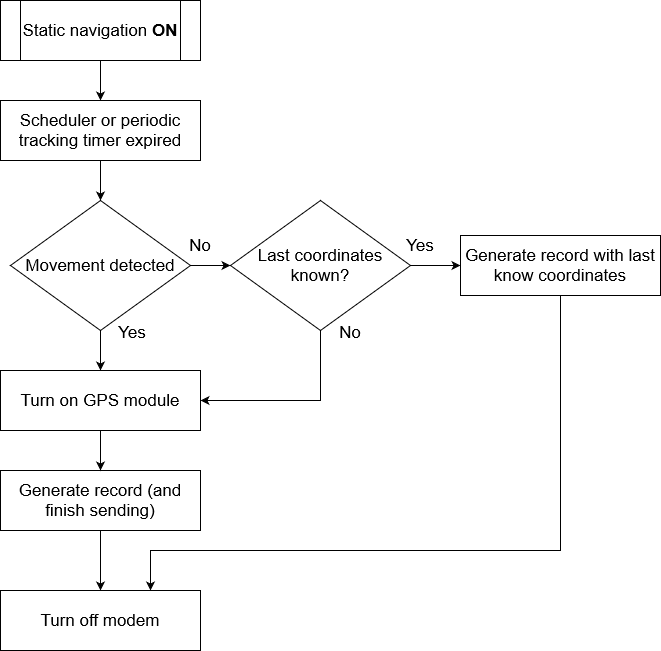
Static navigation helps to save power by not enabling the GPS module and instantly generating a record if movement was not detected.
When enabled the device monitors the accelerometer and registers movement events by configured movement sensitivity. When the device wakes up to save and send a periodic record, and movement was not registered, the device will use the last known coordinates and will generate a record without turning ON the GPS module. However, if there are no last known coordinates, then the device will enable the GPS module and will try to get a new GPS fix.
The functionality is illustrated in the flowchart below:
Movement sensitivity
This feature sets the sensitivity threshold levels for movement event registration. Higher configured level makes the device “less sensitive” and vice versa. Currently, there are 10 configurable Movement Sensitivity levels. Levels are measured in mG - thousandth parts of the gravitational force equivalent or gravitational acceleration of Earth (9.8 m/s). It means that if Movement Sensitivity is set to 1000 mG, the device has to be free falling, experience fierce stops/accelerations or vibrations to detect movement.
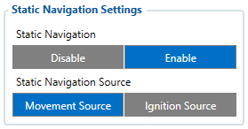
Static Navigation mode is a filter, which filters out track jumps when the object is stationary. If static navigation filter is disabled, it will apply no changes to GPS data. If static navigation filter is enabled, it will filter changes in GPS position if no movement (as defined by configured movement source) or ignition (as defined by configured ignition source) is detected. It allows filtering GPS jumps when the object is parked (not moving) and GPS position is still traced.
Additionally, user can choose which source (movement or ignition) is used to activate/deactivate static navigation.

Static Navigation mode is a filter, which filters out track jumps when the object is stationary. If static navigation filter is disabled, it will apply no changes to GPS data. If static navigation filter is enabled, it will filter changes in GPS position if no movement is detected. It allows filtering GPS jumps when the object is not moving and GPS position is still traced.
Call Duration Limits

These is two places for these settings. First one can be found in the SMS \ Calls Settings section. This setting applies to incoming and outgoing calls, except for the keyboard “Call” action and the Amber Alert feature.

Second one can be found in the Keyboard section. These settings are only visible when the button action is Call. There is only one parameter per button, so the same parameter applies to all button presses.
Ignition Source
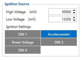
User can choose an ignition source from digital input (1, 2 or 3), power voltage, CAN and accelerometer. More than one ignition source can be selected at the same moment. When there are 2 or more sources selected, at least one condition has to be met to change Ignition status.
For example, DIN1 and Accelerometer are selected as Ignition source. When the device detects movement, Ignition status will change to 1, regardless that DIN1 value is 0.
Ignition status is used in power management and the following functionalities: Eco/Green driving, Excessive idling, Over speeding, Towing detection and trip.
Accelerometer Delay Settings

Here the user can set the movement start/stop delays.
For example, if the Movement Start Delay is set to 1s and Movement Stop Delay to 60s, the movement will be detected after 1s of moving and defined as stopped after 60s when device stopped moving.
| Parameter ID | Name | Min Value | Max Value | Default Value |
|---|---|---|---|---|
| 19001 | Movement Start Delay | 1 | 60 | 5 |
| 19002 | Movement Stop Delay | 5 | 300 | 60 |
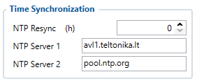
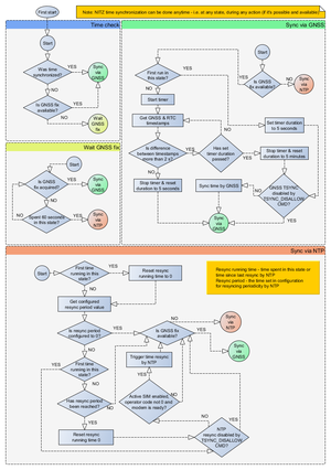
Time Synchronization
Movement Settings

Here the user can set the movement start/stop delays.
For example, if the Movement Start Delay is set to 1s and Movement Stop Delay to 60s, the movement will be detected after 1s of moving and defined as stopped after 60s when device stopped moving. Accelerometer Sensitivity in Sleep parameter defines how much movement device needs to experience to exit sleep mode. The lower the sensitivity - the more movement is required.
Minimal– approximately 40% higher movement threshold comparing to NormalReduced– approximately 20% higher movement threshold comparing to NormalNormal– recommended value for most usersIncreased– approximately 20% lower movement threshold comparing to NormalMaximum– approximately 40% lower movement threshold comparing to Normal
Changing Accelerometer Sensitivity in Sleep parameter might result in fake movement record or skipped movement events! Only change that if you experience problems with movement detection!
Accelerometer Auto Calibration
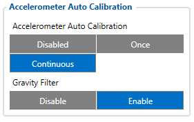
User can disable or enable Accelerometer Auto Calibration and Gravity Filter features. Under Accelerometer Auto Calibration settings, user can choose:
Disable– do not use Auto Calibration feature (sends AXES raw data),Once– calibrate one time only,Continuous– launch Auto Calibration every trip (note: trip function must be enabled! ).
Important!: If Auto Calibration is disabled, device should be mounted according User manual for Eco/Green driving feature to work properly. If enabled, AXES will be reoriented to VEHICLE axes according User manual (+X – Forward, +Y – Left, +Z – Down).
Under Gravity Filter settings, user can choose:
Disabled– do not remove GRAVITY component from AXL/Crash data,Enabled– remove GRAVITY component from AXL/Crash.
(An in-depth explanation for the Auto Calibration can be found here)
Calibration algorithm is used to recalculate accelerometer axes to represent vehicle’s axes (see Picture below). Vehicles axes are as follows:
- X is front.
- Y is left.
- Z is down.
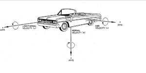
Once vehicle’s axes are calculated, device is considered calibrated. Note: Moving forward along any axis will generate negative values. This means acceleration will generate -X values, accordingly braking will generate X values. Same goes for other axes.
Commands that can be used during calibration:
| Command | Response | Description |
|---|---|---|
| auto_calibrate:set | Yes | Request Auto Calibration task start |
| auto_calibrate:get | Yes | Request calibration info (time, ground vector, side vector) |
| auto_calibrate:clear | Yes | Request calibration clear from flash and stop calibration task |
| auto_calibrate:status | Yes | Request calibration status and calibration task status |
Mounting Guidelines
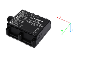
The device should be mounted according to the picture below. Logo/Antenna must be facing up.
Timestamp Backup

Enables or disables the Timestamp Backup synchronization.
This feature, if enabled, every minute saves current timestamp to non-volatile memory (persist after power cutoff). If device was restarted for some reason and was unable to synchronize time, device will use the last saved timestamp as current time.


