Template:FM36YX I/O settings
From Wiki Knowledge Base | Teltonika GPS
Revision as of 09:07, 1 June 2018 by 212.59.13.226 (talk)
When no I/O element is enabled, AVL packet comes with GNSS information only. After enabling I/O element(s) AVL packet along with GNSS information contains current value(s) of enabled I/O element.
| Permanent I/O elements (are always sent to server if enabled) | ||
|---|---|---|
| No. | Property Name | Description |
| 00 | Digital Input Status 1 | Logic: 0 / 1 |
| 01 | Digital Input Status 2 | Logic: 0 / 1 |
| 02 | Digital Input Status 3 | Logic: 0 / 1 |
| 03 | Digital Input Status 4 | Logic: 0 / 1 |
| 04 | Analog Input 1 | Voltage: mV, 0 – 30 V |
| 05 | Digital Output 1 | Logic: 0 / 1 |
| 06 | Digital Output 2 | Logic: 0 / 1 |
| 07 | GNSS PDOP | Probability * 10; 0-500 |
| 08 | GNSS HDOP | Probability * 10; 0-500 |
| 09 | External Voltage | Voltage: mV, 0 – 30 V |
| 10 | GNSS Power | States: 0 – off state (when GPS module is off) 1 – Reserved 2 – GPS ready (antenna is working, but with no GPS fix) 3 – GPS working (antenna is working and has GPS fix) 4 – GPS sleep (when device is in GPS sleep mode) 5 – Overcurrent (The only condition to get value 5, then antenna is damaged and short circuit) |
| 11 | Movement Sensor | 0 – not moving, 1 – moving. |
| 12 | Odometer Value | Distance between two records: m |
| 13 | GSM Operator | Currently used GSM Operator code |
| 14 | Speed (Km/h) | Value in km/h, 0 – xxx km/h |
| 15 | iButton ID | iButton ID number |
| 16 | Mode | 0 – home on stop, 1 – home on move, 2 – roaming on stop, 3 – roaming on move, 4 – unknown on stop, 5 – unknown on move |
| 17 | GSM Signal | GSM signal level value in scale 1 – 5 |
| 18 | Deep Sleep | 0 – not deep sleep mode, 1 – deep sleep mode |
| 19 | Cell ID | GSM base station ID |
Monitoring
I/O monitoring starts after enabling I/O element and setting up I/O parameters as it is shown below:
Event generating
Events happen when the value of enabled I/O intersects thresholds (enter, exit or on both) predefined by High and Low level thresholds. Table below defines all available values of I/O settings.
| Setting | Value |
|---|---|
| Priority | low, high |
| High level | maximum threshold |
| Low level | minimum threshold |
| Generate event | on interval enter, on interval exit, on both enter and exit |
| Average constant | 1 – 232 (4 Bytes) |
Hysteresis
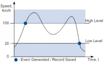
I/O elements can generate events according to hysteresis algorithm. If I/O event operand “Hysteresis” is selected, events will be generated as it is shown in the illustration below (I/O speed is taken as I/O value example):


