Difference between revisions of "Template:FMB640 Features settings"
| Line 93: | Line 93: | ||
Scenario is activated and digital output is ON, when call is received from number which is in authorized numbers list. | Scenario is activated and digital output is ON, when call is received from number which is in authorized numbers list. | ||
Call control functionality: <br/> | Call control functionality: <br/> | ||
| − | * When | + | * When FMM64 is configured to control DOUT1/DOUT2/DOUT3/DOUT4 device waits incoming call from configured secure number. If call is received FMM64 turns on DOUT1/DOUT2/ DOUT3/DOUT4 for user defined Duration timeout (s). If Duration timeout set to „0“(s), DOUT1/DOUT2/ DOUT3/DOUT4 will be OFF. <br/> |
* DOUT1/ DOUT2/DOUT3/DOUT4 can be turned off by Duration timeout (s) or by digital input 1, digital input 2, digital input 3, or digital input 4 (DOUT deactivation settings). <br/> | * DOUT1/ DOUT2/DOUT3/DOUT4 can be turned off by Duration timeout (s) or by digital input 1, digital input 2, digital input 3, or digital input 4 (DOUT deactivation settings). <br/> | ||
* DOUT1/DOUT2/DOUT3/DOUT4 can be turned off before Duration timeout (s) by selected DIN (DOUT deactivation settings).<br/> | * DOUT1/DOUT2/DOUT3/DOUT4 can be turned off before Duration timeout (s) by selected DIN (DOUT deactivation settings).<br/> | ||
* DOUT1/DOUT2/DOUT3/DOUT4 always will be ON, if DOUT deactivation set to DIN1 for example, but DIN1 will be never turned ON or set Duration timeout to Max value (2147483647) it is about 68 years. | * DOUT1/DOUT2/DOUT3/DOUT4 always will be ON, if DOUT deactivation set to DIN1 for example, but DIN1 will be never turned ON or set Duration timeout to Max value (2147483647) it is about 68 years. | ||
| − | {{{pic_DOUTCONTROL|[[Image: | + | {{{pic_DOUTCONTROL|[[Image:FMM640_DOUT_control_via_CALL.png|300px|right]]}}} |
<br/><br/><br/><br/><br/><br/><br/><br/><br/><br/><br/><br/><br/> | <br/><br/><br/><br/><br/><br/><br/><br/><br/><br/><br/><br/><br/> | ||
Revision as of 14:16, 22 August 2019
Green Driving
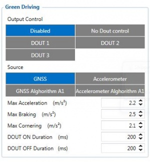
When vehicle parameters exceed the values of Max Acceleration, Max Braking or Max Cornering parameters, the scenario is activated: a record is generated and digital output status is changed to 1 when configured. You can configure all three parameters in m/s2 units. Scenario is activated until current Acceleration, Braking or Cornering value decreases below the set parameter value.
Parameters used with Green Driving functionality are given in a table below.
| Parameter name | Description |
|---|---|
| Scenario Settings | Enable/Disable Green driving functionality |
| Max Acceleration | Value which can be reached while accelerating without triggering harsh acceleration event. |
| Max Braking Acceleration | Value which can be reached while braking without triggering harsh braking event. |
| Max Cornering Acceleration | Value which can be reached while cornering without triggering harsh cornering event. |
| Source | Which source data will be collected from. |
0 – GNSS - GPS Data will be used to detect harsh driving. (This algorithm was used in FM53, FM63 devices)
1 – Accelerometer – Accelerometer data will be used to detect harsh driving. (This algorithm is from FMM device family). Accelerometer calibration needs to be performed with “auto_calibrate:set” command.
2 – GNSS Algorithm A1 – GPS data will be used to detect harsh driving. (This algorithm is used in FMA11 devices). Main difference from FM53 is cornering detection which uses advanced math to more precisely calculate harsh cornering value across different vehicle speeds.
3 – Accelerometer Algorithm A1 - Accelerometer data will be used to detect harsh driving. (This algorithm is used in FMA11 device family)
Note: To use “Accelerometer Algorithm A1” option user need to install device as in Figure 1.
FM64 Devcie accelerometer position. (With positive Z axis pointing to Ground and antennas face forward in vehicle). Before operation with vehicle on level ground user must send “setacc” SMS.
Auto calibration
The auto-calibration process is following:
- The vehicle is stopped.
- There is a straight road ahead.
- Send SMS "auto_calibrate:set" to the FMM device.
- Accelerate to >30 km/h for 5 sec.
- FMM will send a response when calibration is completed successfully.
Calibration is saved to internal flash memory, which means it will stay after a reset. To check auto-calibration status send a following short text message to the FMM device: "auto_calibrate:get".
Over Speeding
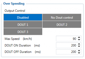
When vehicle speed exceeds configured maximum speed value the scenario is activated, an event record is generated and digital output status is changed to 1 when configured.
Scenario is active until detected speed decreases below the set parameter value.
info
DOUT1, DOUT2 or DOUT3 can be activated for a period of time to warn the driver. Output on-time is configured separately for each feature case. For more information please refer to DOUT controls.
Jamming
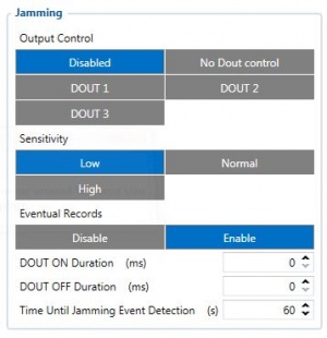
When jamming is detected the scenario is activated, an event record is generated and digital output status is changed to 1 when configured once Jamming timeout runs out. If jamming ends during timeout countdown no event will be generated and output will not be controlled.
Eventual Records parameter can be configured: when it is disabled scenario status value will appear in each AVL record, otherwise it will be appended only to eventual records.
Authorized driving/Immobilizer
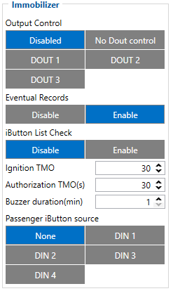
- If DOUT Control is disabled, scenario will only generate events without digital output activation. If DOUT Control is enabled DOUT1/DOUT2 turns ON if ignition turns ON (Ignition Source is configured to 1).
- After any iButton ID is attached, DOUT1/DOUT2/DOUT3 turns OFF.
- After iButton identification configured Ignition Source can be turned OFF (Ignition Source is configured to 0) for no longer than 30 seconds, otherwise immobilizer must be repeated. If * iButton List Check parameter is enabled, authorization will be successful only if the attached iButton is specified in iButton list.
- Ignition off timeout parameter is used to set the duration after which authorization is activated, when ignition is turned off.
- Authorization off timeout parameter is used to set the duration how long the user has time to authorize after switching ignition on.
- iButton list gives ability to use vehicle for 1000 specific iButton owners (specified in iButton list). Selected DOUT is controlled by scenario for user needs, to manage buzzer, LED etc.
iButton Read Notification
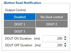
- If scenario is enabled, when iButton is attached and is successfully read, configured DOUT goes ON for configurable amount of time (min: 0.00 s; max: 5.00 s; default: 0.2 s).
- If DOUT ON and DOUT OFF durations are both set to 0, DOUT will be ON until iButton will be removed from the reader.
- If Immobilizer scenario is enabled and iButton’s indication scenario is enabled and the same DOUT controls are chosen then in case iButton is attached DOUT is not affected.
IButton’s event generation works as a standard IO event generation
DOUT Control via Call
Activates DOUT on incoming call
Scenario is activated and digital output is ON, when call is received from number which is in authorized numbers list.
Call control functionality:
- When FMM64 is configured to control DOUT1/DOUT2/DOUT3/DOUT4 device waits incoming call from configured secure number. If call is received FMM64 turns on DOUT1/DOUT2/ DOUT3/DOUT4 for user defined Duration timeout (s). If Duration timeout set to „0“(s), DOUT1/DOUT2/ DOUT3/DOUT4 will be OFF.
- DOUT1/ DOUT2/DOUT3/DOUT4 can be turned off by Duration timeout (s) or by digital input 1, digital input 2, digital input 3, or digital input 4 (DOUT deactivation settings).
- DOUT1/DOUT2/DOUT3/DOUT4 can be turned off before Duration timeout (s) by selected DIN (DOUT deactivation settings).
- DOUT1/DOUT2/DOUT3/DOUT4 always will be ON, if DOUT deactivation set to DIN1 for example, but DIN1 will be never turned ON or set Duration timeout to Max value (2147483647) it is about 68 years.
Short burst data settings
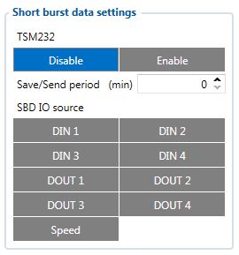
FMB640 supports Iridium devices which can send short burst data (SBD) to server. This means that some data can be sent from FM device to server through satellites.
FMB640 will enable satellite mode only if device can not send data via GPRS. Satellite mode has his own Save/Send period. If timeout is set to 0 no periodic records will be made. It is not recommended to save records often because of satellites traffic price. 8 kilobytes monthly data limit is hardcoded in firmware. If data limit is reached – data limit counter will reset automatically only on next month first day or you can rest counter by SMS command “sbdlimitsreset”.
In addition, you can select which IO element can generate Satellite record. In order to do that you need to go to IO tab select IO record priority Panic and check checkbox “Satellite I/O” what you want to get that data through satellites if there is no GSM connection. Record which will be sent through Iridium satellites network will be different than the regular record. It will contain: 4 bytes timestamp, 3 bytes longitude, 3 bytes latitude, 1 byte record generation info, 1 byte DIN,DOUT info, 1 byte speed value.
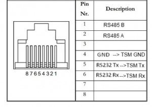
NOTE: Port1/2 cable from FM package can be used for TSM232 connection. For this you need to cut a D-SUB connector and connect wires according instruction above (PIN 4 to TSM GND, PIN5 to TSM Rx, PIN6 to TSM Tx).
NOTE: SBD data is limited to 8000 Bytes per month. For firmware with bigger SBD data limit, please ask your sales manager. If data limit is reached you can reset it with SMS command “sbdlimitsreset”
