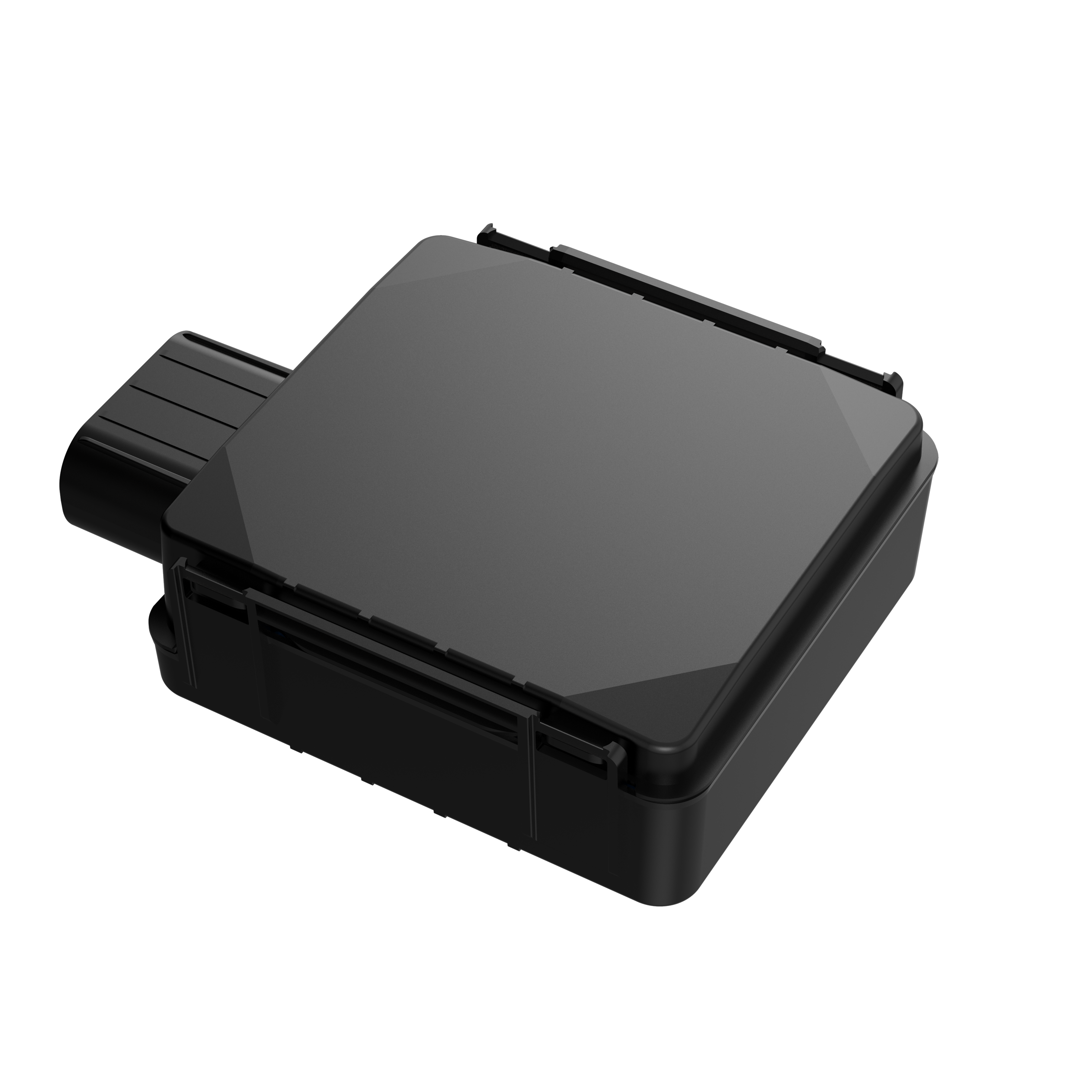
IP67 Case
From Wiki Knowledge Base | Teltonika GPS
Product Specification
| Product Specification | Description |
|---|---|
| Suitable for | FMx125, FMx225, FMx130, FMx230, FMB140, FMB240 |
| Dimensions | 85,0 x 67,0 x 25,6 mm (L x W x H) |
| Ingress Protection Rating | IP67 |
| Color | Black transparent |
| Laser engraving (optional) | Teltonika Telematics branding / without branding |
| Cable | Standard / U-type cable |
| Cable length | 0.9 meters |
How to assemble PCB with IP67 case
- Gently remove top and bottom covers.
- Insert SIM card as shown with PIN request disabled or read our Wiki how to enter it later in Teltonika Configurator. Make sure that SIM card cut-off corner is pointing outward from slot. SIM slot 1 is closer to PCB, SIM slot 2 is the top one.
- Connect battery as shown to device. Position the battery in place where it does not obstruct other components.
- After configuration, see “PC Connection (Windows)”, attach device top and bottom cover back and press them twice to the full closure.
- Make sure that product casing is closed correctly.


 |
This device has an IP67 casing with a two-phase closing, that ensures a reliable protection and ease of use. Please make sure that product casing corner clips are fixed tightly and cable is connected to the device in order to maintain the degree of IP67 protection. |
Battery placement


- Using double sided tape, stick internal battery to the bottom part of the device case. Battery should be glued approximately 15 millimeters from the bottom wall of the case. Picture on the left.
- Connect battery to the PCB.
- Gently place PCB into the bottom case.
Mounting recommendations with U-type cable

• Device fastening
Locate the battery in your vehicle. If present remove the battery cover to access the battery.
You can use a double-sided tape to attach the device on the battery as well as a fastening straps to mount it anywhere next to the battery. Please make sure, that the GNSS antenna and LEDs indicators are facing up Figure.
• Connecting power wire
Device power wire is designed to be directly connected to the positive terminal fastener of the vehicle battery
• Connecting ground wire
Device ground wire is designed to be directly connected to the negative terminal fastener of the vehicle battery.
Mounting recommendations with a standard cable
• Connecting wires:
- Wires should be connected while the module is not plugged in.
- Wires should be fastened to stable wires or other non-moving parts. Any heat emitting and/or moving objects should be kept away from the wires.
- There should be no exposed wires. If factory isolation was removed while connecting the wires, the isolation material should be applied.
- If the wires are placed in the exterior or in places where they can be damaged or exposed to heat, humidity, dirt, etc., additional isolation should be applied and the wires should not be loose.
- Wires cannot be connected to the board computers or control units.
• Connecting power source:
- Be sure that after the car computer goes to sleep mode, power might be still available on the power wires. Depending on the car model, this may happen in 5 to 30 minutes period.
- When the module is connected, measure the voltage again to make sure it did not decrease.
- It is recommended to connect to the main power cable in the fuse box.
- 3 A, 125 V external fuse shall be used.
• Connecting ignition wire:
- Be sure to check if it is a real ignition wire i. e. power does not disappear after starting the engine.
- Check if this is not an ACC wire (when key is in the first position, most of the vehicle electronics are available).
- Check if power is still available when you turn off any of vehicles devices.
- Ignition is connected to the ignition relay output. As alternative, any other relay, which has power output when ignition is on, may be chosen.
• Connecting ground wire:
- Ground wire is connected to the vehicle frame or metal parts that are fixed to the frame.
- If the wire is fixed with the bolt, the loop must be connected to the end of the wire.
- For better contact scrub paint from the spot where loop is going to be connected.

