Universal Device Test Guide: Difference between revisions
ArtiomBolbat (talk | contribs) No edit summary Tag: Manual revert |
|||
| (74 intermediate revisions by 8 users not shown) | |||
| Line 1: | Line 1: | ||
__TOC__ | |||
==''' | =='''<big>Introduction</big>'''== | ||
[[File:Welcome to the telematics banner 1.1.png]] | |||
This Universal Device Test Guide helps new users to get acquainted with Teltonika Telematics Fleet Management devices and to test basic functions in 5 easy steps. | |||
The guide also provides information about specific use cases, advanced features, and software solutions. | |||
Use the [[Main Page|'''Teltonika WIKI''']], [https://community.teltonika.lt/c/teltonika-telematics/6 '''Teltonika Telematics Community page'''] and our [https://www.youtube.com/channel/UCjWIn5amqvtWc7X7tI_04LQ '''Official Youtube Channel'''] to get more in-depth information and answers to any other questions. Our highly professional support engineers are always willing to help - they can be reached via [https://helpdesk.teltonika-iot-group.com/ '''HelpDesk''']. | |||
=='''<big>Basic Testing</big>'''== | |||
[[File:5 easy steps to prepare any Teltonika Telematics device banner.png]] | |||
Here, we will go through five easy testing steps which will introduce you to Teltonika Telematics devices. | |||
We will cover everything you need to start using the device - from inserting a SIM card and powering the device, to receiving GNSS track information from your vehicle to the server. | |||
Equipment and software required to follow this guide: | |||
* Teltonika Telematics device with the included accessories | |||
* Pry tool to open the device enclosure (if needed) | |||
* Working, registered SIM card (type depends on device) | |||
* Power supply unit capable of supplying 10-30 VDC. | |||
* Personal computer with Windows OS, internet connection and: | |||
** COM port drivers (download .zip file [https://wiki.teltonika-gps.com/images/d/d0/TeltonikaCOMDriver.zip '''here''']) | |||
** Latest Microsoft .NET Framework | |||
** Teltonika Configurator software (download the latest version [[Teltonika Configurator versions|'''here''']]) | |||
* One of the following: | |||
** A GNSS tracking service (see overview [[Fleet Management platforms|'''here''']]), and/or | |||
** Teltonika TCP/UDP listener and parser (download the software [[Special:Redirect/file/Protocols and AVL parser pack.zip|'''here''']] (archive password: 1234) | |||
Below is the General Quick Start Guide video. It shows steps that can be applied to most Teltonika Telematics devices. | |||
{| | |||
|- | |||
|''Note!''||''The video shows a configuration procedure with a Truphone SIM and APN. If you use other service providers, please contact them for exact APN details'' | |||
|}<youtube width="850" height="480">GDGFG6Lh1B0</youtube> | |||
==='''STEP 1: Prepare the Device'''=== | |||
'''Result: The SIM card is inserted into the device and the internal battery is connected.''' | |||
Requirements for this step: | |||
* Teltonika Telematics device with the included accessories | |||
* Pry tool to open the device enclosure (if needed) | |||
* Working, registered SIM card (type depends on device) | |||
{| | {| | ||
|- | |- | ||
|[[File:Alert.png|left|link=]]||<b>SIM card | |[[File:Alert.png|left|link=]]||<b>Attention! Power off the device before inserting/removing the SIM card. Disconnect all power sources - internal battery and external voltage. Otherwise, the SIM card may be damaged or the device may not detect it.</b> | ||
|} | |||
All Teltonika Telematics devices use SIM cards to enable telecommunication. It is impossible to get any data from the device to a server without a SIM card. Different devices may use different SIM card types: mini-SIM, micro-SIM, nano-SIM, [[Requirements for eSIM|'''eSIM''']] (soldered during manufacturing). | |||
Some devices have an internal battery. It provides power to the device when no other power sources are available. The battery may not be connected when you receive your device (check your order details). The internal battery must be connected before first use. | |||
==== To insert the SIM card and connect the battery: ==== | |||
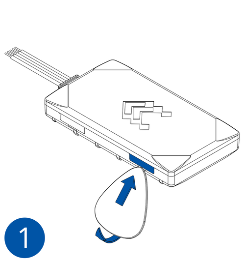
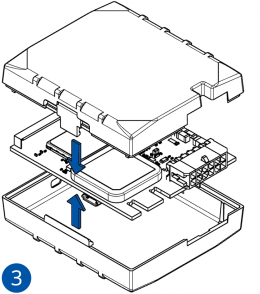
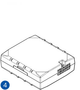
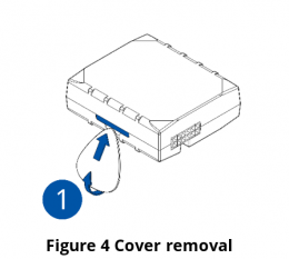
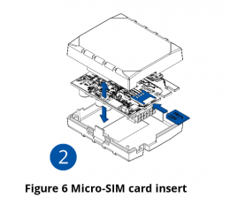
#Look for your device in the device list below and find the related pictures. | |||
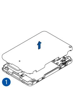
#Carefully remove the device cover - use a pry tool if needed. | |||
#*Some devices have an external SIM card slot. In these cases, first open the slot. | |||
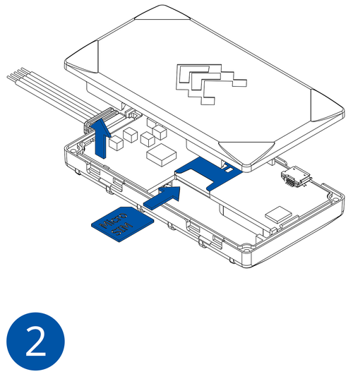
#Insert the SIM card into the SIM card slot. Orient the SIM card correctly - align the cut-off corner. | |||
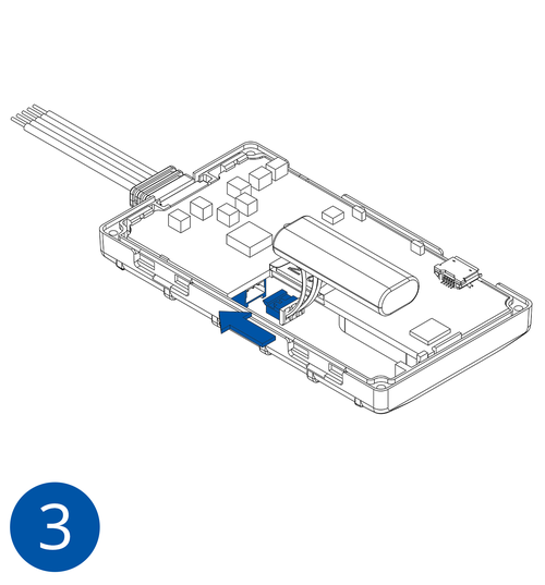
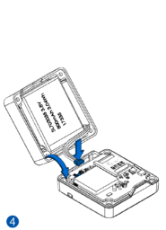
#Connect the battery. Position the battery so that it does not mechanically interfere with other internal components when the cover is closed. | |||
#*Some devices require battery cable management and precise steps to insert the internal components back into the enclosure. | |||
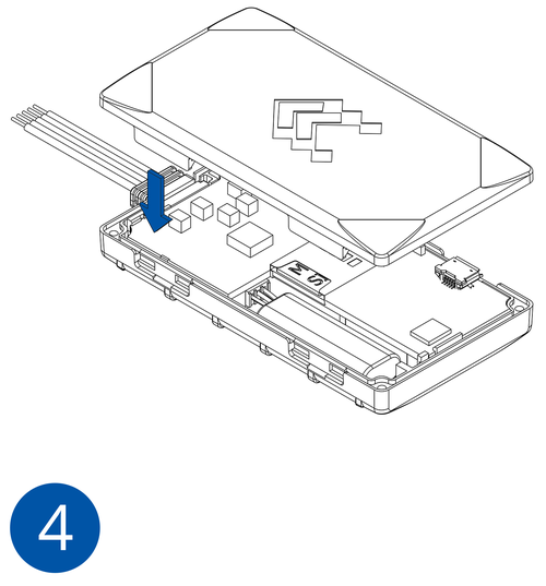
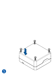
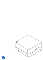
#Re-install the device cover. | |||
The device is now ready to be connected to the PC. | |||
==== Illustrations to help you prepare the device: ==== | |||
<div class="toccolours mw-collapsible mw-collapsed"> | |||
<strong>Basic trackers</strong> | |||
<div class="mw-collapsible-content"> | |||
{| class="wikitable mw-collapsible mw-collapsed" role="presentation" | |||
|<strong>FMB900</strong> | |||
|- | |||
|[[Image:Fmb900_cover_1.png|500px]] | |||
|[[Image:Fmb900_cover_2.png|500px]] | |||
|[[Image:Fmb900_cover_3.png|500px]] | |||
|[[Image:Fmb900_cover_4.png|500px]] | |||
|} | |} | ||
== | {| class="wikitable mw-collapsible mw-collapsed" role="presentation" | ||
|<strong>FMB910, FMB920, FMB930 </strong> | |||
< | |- | ||
|{{{SIM1|[[Image:FMB9_sim_ir_battery_insert-1.png|500px]]}}} | |||
|{{{SIM2|[[Image:FMB9_sim_ir_battery_insert-2.png|500px]]}}} | |||
|{{{SIM3|[[Image:FMB9_sim_ir_battery_insert-3.png|500px]]}}} | |||
|{{{SIM4|[[Image:FMB9_sim_ir_battery_insert-4.png|500px]]}}} | |||
|} | |||
{| class="wikitable mw-collapsible mw-collapsed" role="presentation" | |||
|<strong>FMC920, FMM920 </strong> | |||
|- | |||
|{{{SIM1|[[File:FMC920 1.png|500px]]}}} | |||
|{{{SIM2|[[File:FMC920 2.png|500px]]}}} | |||
|{{{SIM3|[[File:FMC920 3.png|500px]]}}} | |||
|{{{SIM4|[[File:FMC920 4.png|500px]]}}} | |||
|{{{SIM5|[[File:FMC920_5.png|500px]]}}} | |||
|{{{SIM5|[[File:FMC920_6.png|500px]]}}} | |||
|} | |||
< | {| class="wikitable mw-collapsible mw-collapsed" role="presentation" | ||
|<strong>FMB965</strong> | |||
|- | |||
|{{{SIM1|[[Image:FMB965_sim_ir_battery_insert-1.png|260px]]}}} | |||
|{{{SIM2|[[Image:FMB965_sim_ir_battery_insert-2.png|260px]]}}} | |||
|{{{SIM3|[[Image:FMB965_sim_ir_battery_insert-3.png|260px]]}}} | |||
|{{{SIM4|[[Image:FMB965_sim_ir_battery_insert-4.png|260px]]}}} | |||
|{{{SIM4|[[Image:FMB965_sim_ir_battery_insert-5.png|260px]]}}} | |||
|{{{SIM4|[[Image:FMB965_sim_ir_battery_insert-6.png|260px]]}}} | |||
|} | |||
</div> | |||
</div> | |||
=== | <div class="toccolours mw-collapsible mw-collapsed"> | ||
<strong>Fast & Easy trackers</strong> | |||
<div class="mw-collapsible-content"> | |||
{| class="wikitable mw-collapsible mw-collapsed" role="presentation" | |||
|<strong>FMP100</strong> | |||
|- | |||
|[[Image:FMP100 1.png|300px]] | |||
|[[Image:FMP100 2.png|300px]] | |||
|[[Image:FMP100 3.png|300px]] | |||
|[[Image:FMP100 4.png|300px]] | |||
|[[Image:FMP100 5.png|300px]] | |||
|[[Image:FMP1000 6.png|300px]] | |||
|} | |||
{| class="wikitable mw-collapsible mw-collapsed" role="presentation" | |||
|<strong>FMB010</strong> | |||
|- | |||
|{{{insert1|[[Image:Fmb010_cover_1.png|280px]]}}} | |||
|{{{insert2|[[Image:Fmb010_cover_2.png|280px]]}}} | |||
|{{{insert3|[[Image:Fmb010_battery_1.png|280px]]}}} | |||
|{{{insert4|[[Image:Fmb010_cover_3.png|280px]]}}} | |||
|} | |||
{| class="wikitable mw-collapsible mw-collapsed" role="presentation" | |||
|<strong>FMB020</strong> | |||
|- | |||
|{{{insert1|[[Image:Fmb020 card 1.png|280px]]}}} | |||
|{{{insert2|[[Image:Fmb020 card 2.png|280px]]}}} | |||
|{{{insert3|[[Image:Fmb020 card 3.png|280px]]}}} | |||
|{{{insert4|[[Image:Fmb020 card 4.png|280px]]}}} | |||
|} | |||
{| class="wikitable mw-collapsible mw-collapsed" role="presentation" | |||
|<strong>FMC800, FMM800, FMM80A</strong> | |||
|- | |||
|{{{insert1|[[Image:Fmm001_cover_1.png|280px]]}}} | |||
|{{{insert2|[[Image:Fmm0001_cover_2.png|280px]]}}} | |||
|{{{insert3|[[Image:Fmm001_battery_1.png|280px]]}}} | |||
|{{{insert4|[[Image:Fmm001_cover_3.png|280px]]}}} | |||
|} | |||
{| class="wikitable mw-collapsible mw-collapsed" role="presentation" | |||
|<strong>FMT100, FMC880, FMM880</strong> | |||
|- | |||
||[[Image:FMT100_sim_insert-1.png|170px]] [[Image:FMT100_sim_insert-2.png|170px]] | |||
|[[Image:FMT100_sim_insert-3.png|170px]] [[Image:FMT100_sim_insert-4.png|170px]] | |||
|[[Image:FMT100_sim_insert-5.png|170px]] [[Image:FMT100_sim_insert-6.png|170px]] | |||
|} | |||
</div> | |||
</div> | |||
<div class="toccolours mw-collapsible mw-collapsed"> | |||
<strong>Advanced trackers</strong> | |||
<div class="mw-collapsible-content"> | |||
{| class="wikitable mw-collapsible mw-collapsed" role="presentation" | |||
|<strong>FMB110</strong> | |||
|- | |||
|[[Image:{{{sim_insert_pic1|FMB110-Battery-1.png}}}|260px]] | |||
|[[Image:{{{sim_insert_pic2|FMB110-Battery-2.png}}}|260px]] | |||
|[[Image:{{{sim_insert_pic3|FMB110-Battery-3.png}}}|260px]] | |||
|[[Image:{{{sim_insert_pic4|FMB110-Battery-4.png}}}|260px]] | |||
|} | |||
{| class="wikitable mw-collapsible mw-collapsed" role="presentation" | |||
|<strong>FMB120, FMB122, FMB130, FMC130, FMM130</strong> | |||
|- | |||
|[[Image:{{{sim_insert_pic1|FMB1_cover1_correct.png}}}|260px]] | |||
|[[Image:{{{sim_insert_pic2|FMB1_cover2_correct.png}}}|260px]] | |||
|[[Image:{{{sim_insert_pic3|FMB1_cover3_correct.png}}}|260px]] | |||
|[[Image:{{{sim_insert_pic4|FMB1_cover4_correct.png}}}|260px]] | |||
|} | |||
{| class="wikitable mw-collapsible mw-collapsed" role="presentation" | |||
|<strong>FMC13A, FMM13A</strong> | |||
|- | |||
|[[Image:FMC13A_cover1_correct.png|280px]] | |||
|[[Image:FMC13A_cover2_correct.png|280px]] | |||
|[[Image:FMC13A_cover3_correct.png|280px]] | |||
|[[Image:FMC13A_cover4_correct.png|280px]] | |||
|} | |||
{| class="wikitable mw-collapsible mw-collapsed" role="presentation" | |||
|<strong>FMB202, FMB204, FMB209</strong> | |||
|- | |||
|[[Image:case7.png|250px]] | |||
|[[Image:case4.png|250px]] | |||
|[[Image:case2.png|250px]] | |||
|[[Image:case5.png|250px]] | |||
|[[Image:case3.png|250px]] | |||
|[[Image:case6.png|250px]] | |||
|} | |||
== | {| class="wikitable mw-collapsible mw-collapsed" role="presentation" | ||
|<strong>FMB230</strong> | |||
|- | |||
|[[Image:FMX2YX_cover_open1_correct.png|280px]] | |||
|[[Image:FMX2YX_cover2_correct.png|280px]] | |||
|[[Image:FMX2YX cover3 correct.png|280px]] | |||
|[[Image:FMX2YX_cover4_correct.png|280px]] | |||
|[[Image:FMX2YX_cover5_correct.png|middle|280px]] | |||
|[[Image:FMX2YX_cover6_correct.png|middle|280px]] | |||
|} | |||
{| class="wikitable mw-collapsible mw-collapsed" role="presentation" | |||
|<strong>FMC230, FMM230, FMC234</strong> | |||
|- | |||
|[[Image:FMX2YX_cover_open1_correct.png|280px]] | |||
|[[Image:FMX2YX_cover2_correct.png|280px]] | |||
|[[Image:FMX2YX SIM insert FMC230.png|280px]] | |||
|[[Image:FMX2YX_cover4_correct.png|280px]] | |||
|[[Image:FMX2YX_cover5_correct.png|middle|280px]] | |||
|[[Image:FMX2YX_cover6_correct.png|middle|280px]] | |||
|} | |||
</div> | |||
</div> | |||
<div class="toccolours mw-collapsible mw-collapsed"> | |||
| | <strong>OBD trackers</strong> | ||
<div class="mw-collapsible-content"> | |||
{| class="wikitable mw-collapsible mw-collapsed" role="presentation" | |||
|<strong>FMB001</strong> | |||
|- | |- | ||
|{{{insert1|[[Image:Fmb010_cover_1.png|280px]]}}} | |||
|{{{insert2|[[Image:Fmb010_cover_2.png|280px]]}}} | |||
|{{{insert3|[[Image:Fmb010_battery_1.png|280px]]}}} | |||
|{{{insert4|[[Image:Fmb010_cover_3.png|280px]]}}} | |||
|} | |||
{| class="wikitable mw-collapsible mw-collapsed" role="presentation" | |||
|<strong>FMB002, FMB003</strong> | |||
|- | |- | ||
| | |{{{insert1|[[Image:Fmb020 card 1.png|280px]]}}} | ||
|{{{insert2|[[Image:Fmb020 card 2.png|280px]]}}} | |||
|{{{insert3|[[Image:Fmb020 card 3.png|280px]]}}} | |||
|{{{insert4|[[Image:Fmb020 card 4.png|280px]]}}} | |||
| | |||
| | |||
| | |||
|} | |} | ||
{| class="wikitable mw-collapsible mw-collapsed" role="presentation" | |||
|<strong>FMC001, FMC003, FMC00A, FMM001, FMM003, FMM00A</strong> | |||
|- | |||
|{{{insert1|[[Image:Fmm001_cover_1.png|280px]]}}} | |||
|{{{insert2|[[Image:Fmm0001_cover_2.png|280px]]}}} | |||
|{{{insert3|[[Image:Fmm001_battery_1.png|280px]]}}} | |||
|{{{insert4|[[Image:Fmm001_cover_3.png|280px]]}}} | |||
|} | |||
</div> | |||
</div> | |||
[[ | <div class="toccolours mw-collapsible mw-collapsed"> | ||
<strong>CAN trackers</strong> | |||
<div class="mw-collapsible-content"> | |||
{| class="wikitable mw-collapsible mw-collapsed" role="presentation" | |||
|<strong>FMB140, FMC150, FMM150</strong> | |||
|- | |||
|[[Image:{{{sim_insert_pic1|FMB1_cover1_correct.png}}}|260px]] | |||
|[[Image:{{{sim_insert_pic2|FMB1_cover2_correct.png}}}|260px]] | |||
|[[Image:{{{sim_insert_pic3|FMB1_cover3_correct.png}}}|260px]] | |||
|[[Image:{{{sim_insert_pic4|FMB1_cover4_correct.png}}}|260px]] | |||
|} | |||
{| class="wikitable mw-collapsible mw-collapsed" role="presentation" | |||
|<strong>FMB240</strong> | |||
|- | |||
|[[Image:FMX2YX_cover_open1_correct.png|280px]] | |||
|[[Image:FMX2YX_cover2_correct.png|280px]] | |||
|[[Image:FMX2YX SIM insert FMC230.png|280px]] | |||
|[[Image:FMX2YX_cover4_correct.png|280px]] | |||
|[[Image:FMX2YX_cover5_correct.png|middle|280px]] | |||
|[[Image:FMX2YX_cover6_correct.png|middle|280px]] | |||
|} | |||
</div> | |||
</div> | |||
[[ | <div class="toccolours mw-collapsible mw-collapsed"> | ||
<strong>Professional trackers</strong> | |||
<div class="mw-collapsible-content"> | |||
{| class="wikitable mw-collapsible mw-collapsed" role="presentation" | |||
|<strong>FMB641</strong> | |||
|- | |||
|[[Image:Fmb640FMB640111.png|260px]] | |||
|[[Image:Fmb640-FMB640222.png|260px]] | |||
|[[Image:Fmb640FMB640333.png|260px]] | |||
|[[Image:Fmb640FMB640444.png|260px]] | |||
|} | |||
{| class="wikitable mw-collapsible mw-collapsed" role="presentation" | |||
|<strong>FMC650, FMM650</strong> | |||
|- | |||
|[[Image:{{{sim_insert_pic1|{{{model|Fmb640}}}-cover-1.png}}}|260px]] | |||
|[[Image:{{{sim_insert_pic2|{{{model|Fmb640}}}-cover-2.png}}}|260px]] | |||
|[[Image:{{{sim_insert_pic3|{{{model|Fmb640}}}-cover-3.png}}}|260px]] | |||
|[[Image:{{{sim_insert_pic4|{{{model|Fmb640}}}-cover-4.png}}}|260px]] | |||
|[[Image:{{{sim_insert_pic4|{{{model|Fmb640}}}-cover-5.png}}}|260px]] | |||
|[[Image:{{{sim_insert_pic4|{{{model|Fmb640}}}-cover-6.png}}}|260px]] | |||
|} | |||
[[Image:{{{ | {| class="wikitable mw-collapsible mw-collapsed" role="presentation" | ||
|<strong>FMB125, FMC125, FMM125</strong> | |||
|- | |||
|[[Image:{{{sim_insert_pic1|FMB1_cover1_correct.png}}}|260px]] | |||
|[[Image:{{{sim_insert_pic2|FMB122-Battery-Sim-2.png}}}|260px]] | |||
|[[Image:{{{sim_insert_pic3|FMB1_cover3_correct.png}}}|260px]] | |||
|[[Image:{{{sim_insert_pic4|FMB1_cover4_correct.png}}}|260px]] | |||
|} | |||
{| class="wikitable mw-collapsible mw-collapsed" role="presentation" | |||
|<strong>FMC225</strong> | |||
|- | |||
|[[Image:FMX2YX_cover_open1_correct.png|280px]] | |||
|[[Image:FMX2YX_cover2_correct.png|280px]] | |||
|[[Image:FMX2YX SIM insert FMC230.png|280px]] | |||
|[[Image:FMX2YX_cover4_correct.png|280px]] | |||
|[[Image:FMX2YX_cover5_correct.png|middle|280px]] | |||
|[[Image:FMX2YX_cover6_correct.png|middle|280px]] | |||
|} | |||
</div> | |||
</div> | |||
<div class="toccolours mw-collapsible mw-collapsed"> | |||
<strong>Autonomous trackers</strong> | |||
<div class="mw-collapsible-content"> | |||
{| class="wikitable mw-collapsible mw-collapsed" role="presentation" | |||
|<strong>TAT100, TAT140, TAT240</strong> | |||
|- | |||
|[[Image:TAT100 Cover off.png|275px]] | |||
|[[Image:TAT100 SIM in.png|275px]] | |||
|[[Image:TAT100 Device on V3.png|275px]] | |||
|[[Image:TAT100 Cover on.png|275px]] | |||
|} | |||
== | {| class="wikitable mw-collapsible mw-collapsed" role="presentation" | ||
|<strong>TMT250</strong> | |||
|- | |||
|[[Image:Tmt250battery1.png|185px]] | |||
|[[Image:Tmt250battery2.png|185px]] | |||
|[[Image:Tmt250battery3.png|185px]] | |||
|[[Image:Tmt250battery4.png|185px]] | |||
|[[Image:Tmt250battery5.png|185px]] | |||
|[[Image:Tmt250battery6.png|185px]] | |||
|} | |||
{| class="wikitable mw-collapsible mw-collapsed" role="presentation" | |||
|<strong>GH5200</strong> | |||
|- | |||
|[[Image:GH5200 battery sim insert-1.jpg|250px]] | |||
|[[Image:GH5200 battery sim insert-2.jpg|250px]] | |||
|[[Image:GH5200 battery sim insert-3.jpg|250px]] | |||
|[[Image:GH5200 battery sim insert-4.jpg|250px]] | |||
|} | |||
</div> | |||
</div> | |||
<div class="toccolours mw-collapsible mw-collapsed"> | |||
<strong>E-Mobility trackers</strong> | |||
<div class="mw-collapsible-content"> | |||
{| class="wikitable mw-collapsible mw-collapsed" role="presentation" | |||
|<strong>TST100</strong> | |||
|- | |||
|[[Image:TST100_setup_1.jpg|250px]] | |||
|[[Image:TST100_setup_2.jpg|250px]] | |||
|[[Image:TST100_setup_3.jpg|250px]] | |||
|[[Image:TST100_setup_4.jpg|250px]] | |||
|[[Image:TST100_setup_5.png|250px]] | |||
|[[Image:TST100_setup_6.jpg|250px]] | |||
|[[Image:TST100_setup_7.jpg|250px]] | |||
|} | |||
{| class="wikitable mw-collapsible mw-collapsed" role="presentation" | |||
|<strong>TFT100</strong> | |||
|- | |||
|[[Image:Cover1.png|250px]] | |||
|[[Image:Cover2.png|250px]] | |||
|[[Image:Cover3.png|250px]] | |||
|[[Image:Cover4.png|250px]] | |||
|[[Image:Cover5.png|250px]] | |||
|} | |||
</div> | </div> | ||
</div> | |||
==='''STEP 2: Connect the Device to PC'''=== | |||
'''Result: The device is powered with a power supply and connected to the PC.''' | |||
Requirements for this step: | |||
* Prepared Teltonika Telematics device | |||
* Personal computer with Windows OS, internet connection and: | |||
** COM port drivers (download .zip file [https://wiki.teltonika-gps.com/images/d/d0/TeltonikaCOMDriver.zip '''here''']) | |||
* A power supply unit capable of supplying 10-30 VDC. | |||
One of the ways to control your device is by connecting it to a PC via USB or Bluetooth®. Before connecting, power must be provided to the device by a power supply. | |||
For device-specific information about connecting to PC, see [[Main Page|'''Wiki Knowledge Base''']] → ''Your device model'' → First Start → PC Connection (Windows). | |||
==== To connect the device to the PC: ==== | |||
# Install COM port drivers. | |||
# <u>Before</u> connecting the device to the power supply and turning the power supply on, make sure that the power supply will provide voltage in the range of 10-30 VDC, e.g. 12 VDC. | |||
# Do not turn on the power supply. Connect the device to the power supply using the provided power cable. | |||
#* Some devices can be powered and configured using only a USB cable, without the need for a separate power supply (in this case, skip to the last step). | |||
# Now, turn on the power supply – device LEDs should start blinking (see [[LED Status|'''LED Status''']]). | |||
# Connect the device to the PC via the provided USB cable or Bluetooth®. | |||
The device is now powered and connected to the PC. | |||
==='''STEP 3: Configure the Device'''=== | |||
'''Result: The device is configured to generate and send records to a specified server.''' | |||
Requirements for this step: | |||
* Teltonika Telematics device connected to the PC | |||
* PC with Windows OS and latest Microsoft .NET Framework. | |||
* Teltonika Configurator software (download the latest version [[Teltonika Configurator versions|'''here''']]). | |||
Every Teltonika Telematics device is pre-configured with default factory settings. Use the [[Teltonika Configurator Introduction|'''Teltonika Configurator''']] software and easily change device settings to meet your specific needs. | |||
Here, we go through the most important features of the Configurator: | |||
* Starting the Configurator. | |||
* Using the most important menus: Status, System, GPRS, and Data Acquisition. | |||
* | |||
==== Start the Configurator ==== | |||
On your PC, start the Configurator and select your connected device. | |||
[[File:Faceless_configurator_select.png|370x370px]] | |||
The primary window opens. It contains three areas: | |||
# Top area - loading and saving configurations, updating firmware, and other actions. | |||
# Left-side area - shows menus containing various device settings. Each device may have a different set of settings. | |||
# Main area - here, the settings will show up when you click on a menu. | |||
{| | |||
|- | |||
|'''''Important!'''''||<b>''After making changes to the configuration, save them by clicking “Save to device.”To restore the configuration to default factory settings, click “Reset configuration”.''</b> | |||
<b>''To disconnect from the device, click the device button (top right).''</b> | |||
|} | |||
== | ==== Status Menu ==== | ||
The Status menu contains general device information. View statuses of the main systems, such as GNSS and GSM, in separate tabs. | |||
[[File:GNSS Info.png|frameless|550x550px]][[File:GSM Info.png|frameless|549x549px]] | |||
{| class="wikitable" | |||
|+Status menu overview | |||
!Tab in Status menu | |||
!Description | |||
!Most important parameters to watch | |||
|- | |||
| rowspan="2" |GNSS info | |||
| rowspan="2" |Shows status of GNSS module and the fix status, counts for packets and satellites, location information. | |||
|Module Status – shows whether the GNSS module is ON or in one of the Sleep modes. | |||
|- | |||
|Fix Status – shows if a satellite fix is available. | |||
Make sure that the device is facing an open sky - at least four visible satellites are required for a GNSS fix. | |||
|- | |||
| rowspan="3" |GSM info | |||
| rowspan="3" |Shows GSM modem and SIM status, signal level, record sending timestamps, GPRS traffic and SIM data, sockets. | |||
|Signal Level – shows the signal level. | |||
Make sure that signal is available – this allows the device to successfully send data to the server. | |||
|- | |||
|Type – shows the type of GPRS connection. | |||
|- | |||
|Socket – shows socket information (“Closed”, or the server domain and port used to send AVL data via TCP/UDP). | |||
|- | |||
|I/O info | |||
| colspan="2" |Shows current values from all configurable I/O elements. | |||
|- | |||
|Maintenance | |||
| colspan="2" |Allows capturing data logs, accelerometer data, and calibrating LLS sensors. | |||
|} | |||
=== | ==== System Menu ==== | ||
The System menu contains global settings that control the general operation of the tracking device. | |||
{| class="wikitable" | |||
|+ | |||
Note on “Saving/Sending Records Without Time Sync” for testing purposes | |||
|[[File:Testing_always_sending.png|alt=|frameless]] | |||
|''Locate the “System Settings” area.'' | |||
''For testing purposes, set the “Saving/Sending Records Without Time Sync” setting to “Always”.'' | |||
''This will allow the device to send data without a GNSS fix and/or time synchronization (which may happen when testing the device indoors, e.g. in an office).'' | |||
|} | |||
==== GPRS Menu ==== | |||
The GPRS menu allows configuring server and GPRS settings. | |||
{| class="wikitable | With a correct GPRS/server setting configuration, the device will synchronize time, and update records to the configured server. The device will do this based on time intervals set in the Data Acquisition menu (see below). | ||
|+ | {| | ||
|- | |||
|''Note!''||''If you have not yet set up a GNSS tracking service, you can use Teltonika TCP/UDP listener (to receive data from the device) and Teltonika parser (to parse the received information). Download the software [[Special:Redirect/file/Protocols and AVL parser pack.zip|'''here''']] (archive password: 1234).'' | |||
|} | |||
The table below describes the most important parameters in the GPRS menu. This is the minimal required configuration for a device to start sending data to your server. | |||
{| class="wikitable" | |||
|+GPRS menu overview | |||
!Figure | |||
!Area | |||
!Parameter ID | |||
!Parameter description | |||
|- | |- | ||
| | | rowspan="3" |[[File:GPRS_settings.png|alt=|frameless|400x400px]] | ||
| style=" | | rowspan="3" |GPRS Settings | ||
|<span style="background-color:#91b9d4;">2001</span> | |||
|APN (Access Point Name) – a gateway between mobile operator and the public internet. | |||
The device connects to the internet when current APN settings are entered. | |||
Obtain the APN from your SIM card provider. | |||
Some devices support the Auto APN feature, see [[Auto APN feature for FM trackers|'''here''']] for more information. | |||
|- | |- | ||
| style=" | |<span style="background-color:#91d4b9;">2002</span> | ||
| | |APN username (leave the field empty if there is no APN username). | ||
|- | |- | ||
| style=" | |<span style="background-color:#b991d4;">2003</span> | ||
| | |APN password (leave the field empty if there is no APN password). | ||
|- | |- | ||
| | | rowspan="3" |[[File:SERVER_settings.png|alt=|frameless|400x400px]] | ||
| style=" | | rowspan="3" |Server Settings | ||
|<span style="background-color:#b9d491;">2004</span> | |||
|Domain/IP address of destination server. | |||
|- | |- | ||
| style=" | |<span style="background-color:#d491b9;">2005</span> | ||
| | |Port of destination server. | ||
|- | |- | ||
| style="text- | |<span style="background-color:#d4b991;">2006</span> | ||
| | |Protocol for sending data to the destination server (0 – TCP, 1 - UDP). | ||
|} | |||
You can also quickly set up your device GPRS settings via SMS. Send the following SMS command. The highlighted parameter IDs are explained in the table above. Make sure to insert two space symbols before SMS text: | |||
" setparam <span style="background-color:#91b9d4;">2001</span>:APN;<span style="background-color:#91d4b9;">2002</span>:APN_username;<span style="background-color:#b991d4;">2003</span>:APN_password;<span style="background-color:#b9d491;">2004</span>:Domain;<span style="background-color:#d491b9;">2005</span>:Port;<span style="background-color:#d4b991;">2006</span>:0" | |||
[[File:SMS_testing.png|alt=Communcation between user and device via SMS|none|thumb|347x347px|Communication between user and device via SMS]] | |||
==== Data Acquisition Menu ==== | |||
The Data Acquisition menu allows configuring how the device acquires data based on the operator type and movement source. | |||
The device will generate periodic records and send them to the server based on the Data Acquisition settings. The default device configuration has optimal parameters pre-configured for best track quality and data usage. | |||
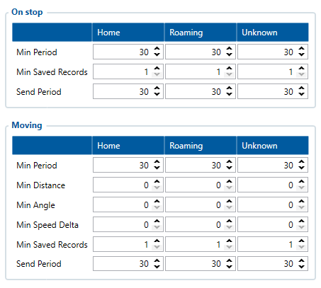
For testing purposes, set certain parameters according to the table below. As can be seen, here we configure the device to make records every 30 seconds and send them also every 30 seconds. The device will switch operating modes (between “On Stop” and “Moving”) based on the status of configured movement source. | |||
After testing, configure Data Acquisition settings according to your needs. For more detailed information about configuring your device using the Teltonika Configurator, see [[Main Page|'''Wiki Knowledge Base''']] → Y''our device model'' → Configuration. | |||
The table below describes the most important parameters in the Data Acquisition menu. | |||
{| class="wikitable" | |||
|+Data Acquisition menu overview | |||
!Figure ('''Recommended Data Acquisition settings for device testing''') | |||
!'''Parameter ID''' | |||
!'''Parameter description''' | |||
|- | |||
| rowspan="3" |[[File:Testing_Data_Acquisition_V2.png|alt=]] | |||
|10000 | |||
|Min Period –the minimal time interval (seconds) between record acquisition. The device will acquire new records every Min Period seconds. | |||
|- | |||
|10004 | |||
|Min Saved Records – the minimum number of records that can be sent to the server in one data packet. The device will send no less that Min Saved Records every Min Period seconds. | |||
|- | |||
|10005 | |||
|Send Period – the time interval (seconds) after which the device checks whether it has generated enough records (based on the Min Saved Records parameter). | |||
''Note! If the link with the server is open, records are sent to the server immediately after they are generated. Send Period setting is only used to trigger data sending if the link with the server is closed.'' | |||
|} | |||
==='''STEP 4: Mount the Device'''=== | |||
'''Result: The device is mounted in an optimal location, with good GNSS and GSM connectivity.''' | |||
Requirements for this step: | |||
* Teltonika Telematics device with a basic configuration | |||
* The tracked object (vehicle, asset) (if available) | |||
Every Teltonika Telematics device has specific mounting instructions. Some devices are plug-and-play, while hard-wired devices require professional installation. | |||
For detailed information about wiring your specific device, see [[Main Page|'''Wiki Knowledge Base''']] → ''Your device model'' → First Start → Mounting recommendations and precautions. | |||
The most important mounting recommendations are: | |||
* For vehicles, if possible, mount the device under the plastic panel behind the front window. | |||
* The Teltonika logo on the device should be facing the sky – this orients the antennas of the device for best signal reception. | |||
* Make sure that no metal parts surround the device – metal may negatively impact signal reception. | |||
Below is an example illustration for mounting a device. | |||
[[File:Mounting picture 02-01.png|frameless|806x806px]] | |||
==='''STEP 5: Track the Device'''=== | |||
'''Result: The user tracks their device on a tracking platform.''' | |||
Requirements for this step: | |||
* Teltonika Telematics device with a basic configuration | |||
* A user account on one of the supported tracking platforms, or | |||
* Access to a router and a TCP/UDP listener | |||
The last step in basic testing is to get data from your device to a tracking platform. | |||
Do this by using pre-made tracking platforms (see [[Fleet Management platforms|'''here''']]), or simple TCP/UDP listeners. | |||
To set up a simple TCP/UDP listener on your personal computer: | |||
# Open a TCP/UDP port (see [[Opening TCP/UDP port|'''here''']]). | |||
# Do the steps according to [[Java Parser First Start Guide|'''Java Parser First Start Guide''']]. | |||
The illustrations below show a device track on different pre-made tracking platforms. | |||
[[File:TAVL jamming.png]] | |||
[[File:Wialonturbo.jpg]] | |||
=='''<big>Advanced Testing</big>'''== | |||
[[File:Discover more device possibilities in-depth banner.png]] | |||
Here, we review certain advanced functionalities that allow you to get the most out of your Teltonika Telematics device. | |||
This advanced testing guide is only an example – available functionalities allow accomplishing much more! | |||
==='''Parameter IDs and Advanced SMS capabilities'''=== | |||
[[File:WIKI_hover.gif|alt=|right]] | |||
All of the parameters mentioned in the guide above (and many more) have a name and an ID (unique identifier). The parameter ID consists of 3 or 5 digits. See a detailed list of parameters and their IDs [[FMB Device Family Parameter list|'''here''']]. You can also find a relevant parameter ID by hovering your mouse pointer over a specific parameter in the Configurator. | |||
Parameters of Teltonika Telematics devices may be configured and read via SMS. | |||
Teltonika Telematics devices offer a wide range of SMS configuration and debugging features - see the full list of SMS commands [[FMB SMS/GPRS Commands|'''here''']]. | |||
SMS command length is limited to 160 characters. | |||
The general SMS command structure is: | |||
<SMS_Login>''<space>''<SMS_Password>''<space>''<Command>''<space>''[Parameter ID]''':'''[New Parameter Value]''';'''[Parameter ID]''':'''[New Parameter Value]... | |||
* A space symbol separates these elements: SMS login, password, command name, the first parameter:value pair | |||
* A colon symbol separates the parameter ID and the new parameter value | |||
* Multiple parameter values can be changed with one SMS command – a semicolon symbol separates parameter:value pairs. | |||
If no login name and password are set in the device configuration, just omit them in the SMS command. I.e., the command should start with two spaces, followed by the command name. | |||
As an example, let us take one of the most widely used SMS commands: “setparam”. It changes a parameter value, e.g.: | |||
* If a login and password are set: | |||
<SMS_Login><space><SMS_Password><space>setparam<space>101:1 | |||
This SMS command will change the parameter “101” (Ignition settings) to “1” (DIN1). | |||
* If no login and password are set: | |||
<space><space>setparam<space>101:2;138:1 | |||
This SMS command will change the parameter “101” (Ignition settings) to “2” (Accelerometer) and parameter “138” (Movement source) to “1” (Ignition). | |||
==='''Advanced Use Cases'''=== | |||
Beyond basic configuration, Teltonika Telematics devices can be configured as intricately as you require. Most devices can cover a broad spectrum of use cases, while others are highly specialized. | |||
General and specific use cases are presented in the links below. Each category explains what parameters must be configured and why. Where applicable, we provide examples of what information would be available on your server and how to read it. | |||
* General use cases are presented on the Teltonika Telematics website [https://teltonika-gps.com/industries/use-cases/ '''here''']. | |||
* Specific technical usage scenarios are presented on the Telematics Wiki [[Usage scenarios|'''here''']]. | |||
=='''<big>Solutions</big>'''== | |||
[[File:Extend device's capabilities with our solutions banner.png]] | |||
Here, we overview Teltonika Telematics solutions to remotely access, manage and control devices, including external devices, such as tachographs. | |||
==='''FOTA WEB'''=== | |||
FOTA WEB is a SaaS solution for the remote, OTA (over-the-air) management of Teltonika Telematics devices.<youtube width="850" height="480">SiMwnkEEes4</youtube> | |||
FOTA WEB allows you to: | |||
* Access your devices through a Web browser on any device | |||
* Upgrade device firmware | |||
* Change the configuration | |||
* Remotely debug FMx devices | |||
* Update CAN adapters without a dedicated application | |||
* Upload a CAN configuration to some devices | |||
For more information, see [[FOTA WEB|'''here''']]. | |||
FOTA WEB is compatible with all currently sold products and is available for all direct Teltonika Telematics customers. Contact Teltonika Telematics sales representatives to obtain access to FOTA WEB. FOTA WEB meets all GDPR requirements. | |||
{| | |||
|- | |- | ||
| | |''Note!''||''A desktop solution – FOTA – is a predecessor to FOTA WEB. It is mainly used to update EOL (end-of-life) devices. We strongly recommend to use the newest version of FOTA WEB to perform OTA management.'' | ||
| | |||
|} | |} | ||
==='''WEB Tacho'''=== | |||
WEB Tacho is an online service that allows to download tachograph files from supported tachographs (using Teltonika Telematics Professional trackers). | |||
The files are first stored on a server, in defined formats (.DDD, .V1B, .C1B, .TGD). The files then can be obtained in various ways: downloaded directly to a PC or to a pre-defined FTP server, or sent to e-mail. | |||
For more information, see [[WEB Tacho|'''here''']]. | |||
Contact Teltonika Telematics sales representatives to obtain access to WEB Tacho. | |||
=='''<big>Protocols</big>'''== | |||
[[File:Understand communication language banner.png]] | |||
Here, we introduce the communication protocols used by Teltonika Telematics devices. | |||
All Teltonika Telematics devices communicate with servers using specialized protocols, called “codecs”. Each protocol has a particular structure and application scenario. E.g., [[Codec#Codec%208%20Extended|'''Codec 8 Extended''']] is used for one-way device to server data transmission, while [[Codec#Codec%20for%20communication%20over%20GPRS%20messages|'''Codec 12''']] is used for two-way device-server communication via GPRS messages. | |||
More general information about the various protocols can be found [[Codec|'''here''']]. | |||
[[Category:General Information]] | |||
Revision as of 10:02, 3 January 2025
Main Page > General Information > Universal Device Test GuideIntroduction
This Universal Device Test Guide helps new users to get acquainted with Teltonika Telematics Fleet Management devices and to test basic functions in 5 easy steps.
The guide also provides information about specific use cases, advanced features, and software solutions.
Use the Teltonika WIKI, Teltonika Telematics Community page and our Official Youtube Channel to get more in-depth information and answers to any other questions. Our highly professional support engineers are always willing to help - they can be reached via HelpDesk.
Basic Testing
Here, we will go through five easy testing steps which will introduce you to Teltonika Telematics devices.
We will cover everything you need to start using the device - from inserting a SIM card and powering the device, to receiving GNSS track information from your vehicle to the server.
Equipment and software required to follow this guide:
- Teltonika Telematics device with the included accessories
- Pry tool to open the device enclosure (if needed)
- Working, registered SIM card (type depends on device)
- Power supply unit capable of supplying 10-30 VDC.
- Personal computer with Windows OS, internet connection and:
- One of the following:
Below is the General Quick Start Guide video. It shows steps that can be applied to most Teltonika Telematics devices.
| Note! | The video shows a configuration procedure with a Truphone SIM and APN. If you use other service providers, please contact them for exact APN details |
STEP 1: Prepare the Device
Result: The SIM card is inserted into the device and the internal battery is connected.
Requirements for this step:
- Teltonika Telematics device with the included accessories
- Pry tool to open the device enclosure (if needed)
- Working, registered SIM card (type depends on device)
 |
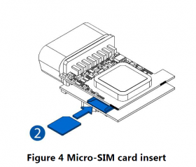
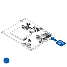
Attention! Power off the device before inserting/removing the SIM card. Disconnect all power sources - internal battery and external voltage. Otherwise, the SIM card may be damaged or the device may not detect it. |
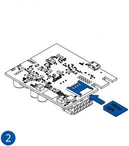
All Teltonika Telematics devices use SIM cards to enable telecommunication. It is impossible to get any data from the device to a server without a SIM card. Different devices may use different SIM card types: mini-SIM, micro-SIM, nano-SIM, eSIM (soldered during manufacturing).
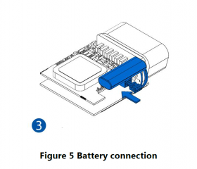
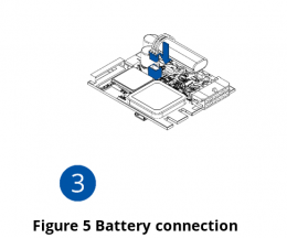
Some devices have an internal battery. It provides power to the device when no other power sources are available. The battery may not be connected when you receive your device (check your order details). The internal battery must be connected before first use.
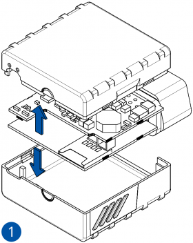
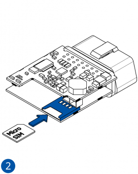
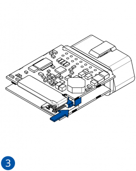
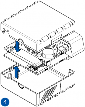
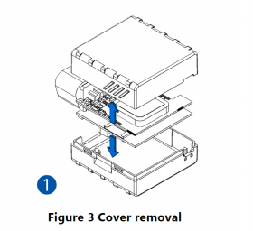
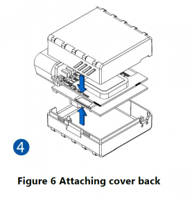
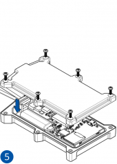
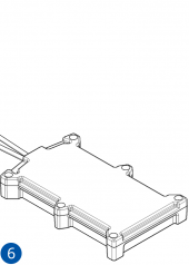
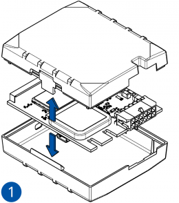
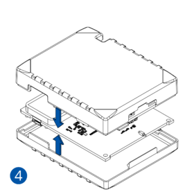
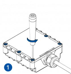
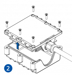
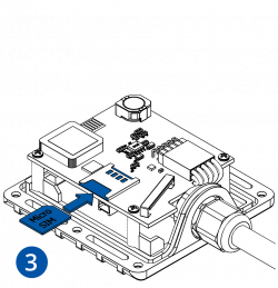
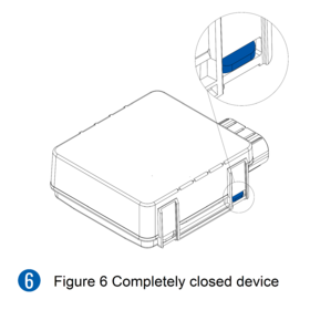
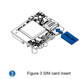
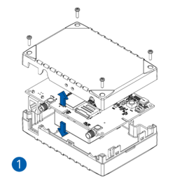
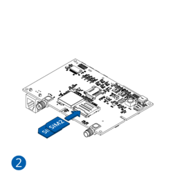
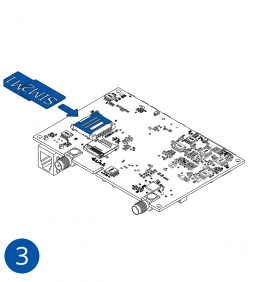
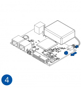
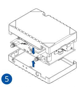
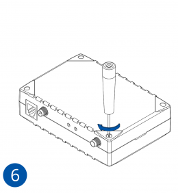
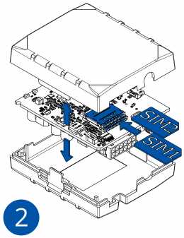
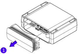
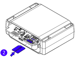
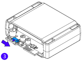
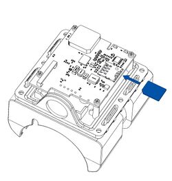
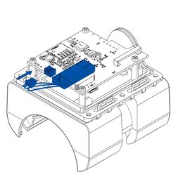
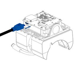
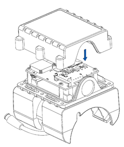
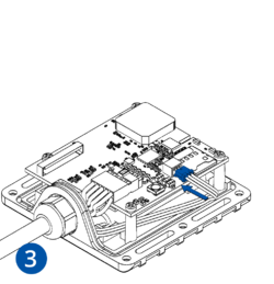
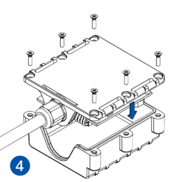
To insert the SIM card and connect the battery:
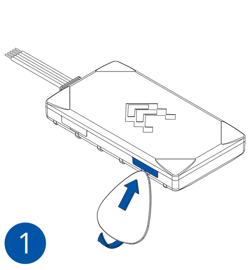
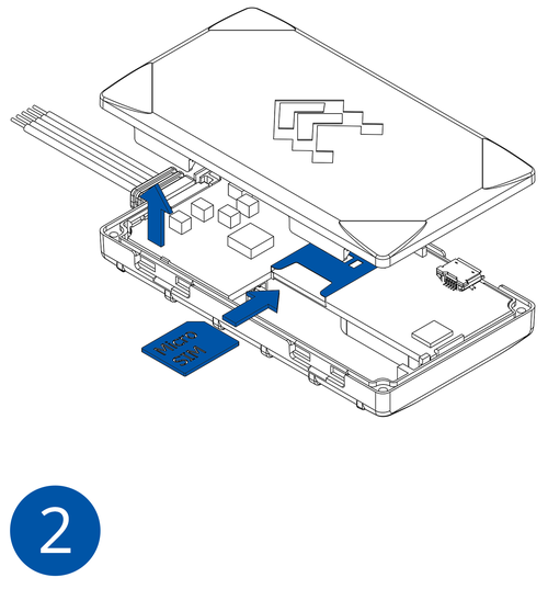
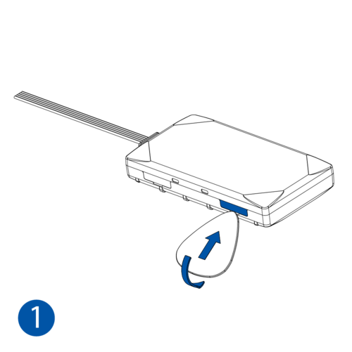
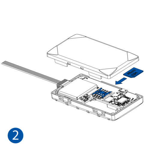
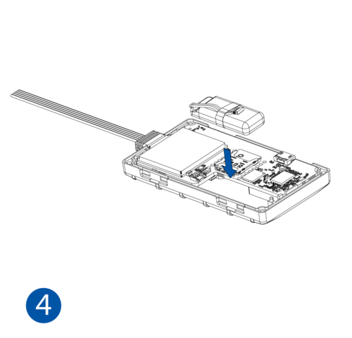
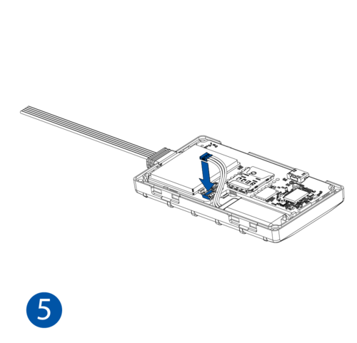
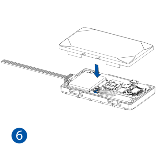
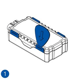
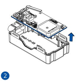
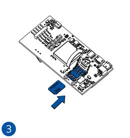
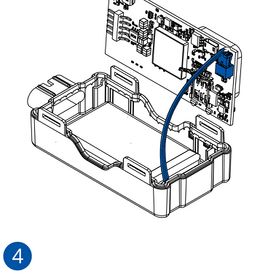
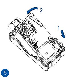
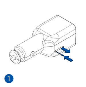
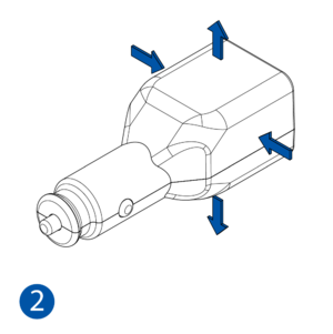
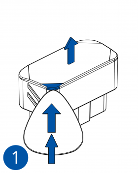
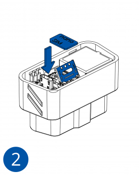
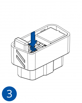
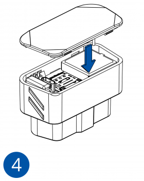
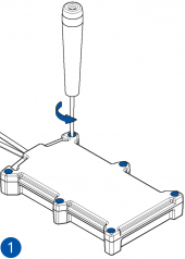
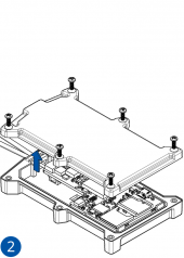
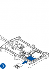
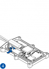
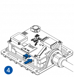
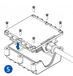
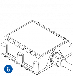
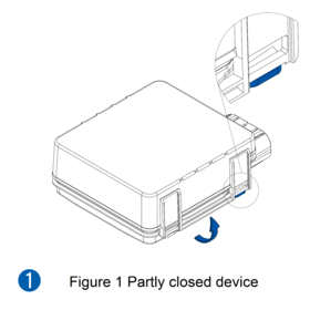
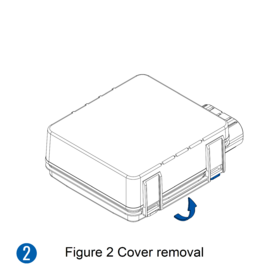
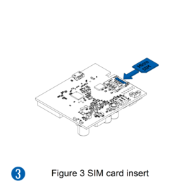
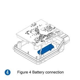
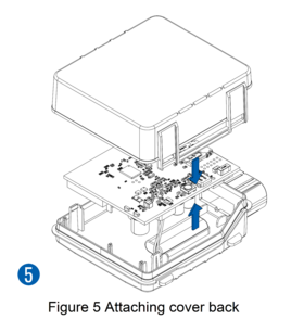
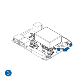
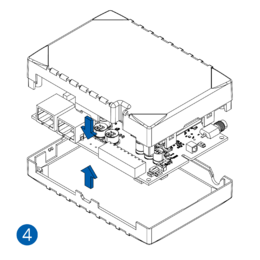
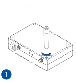
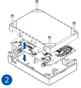
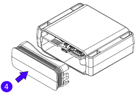
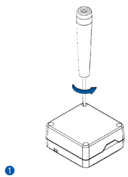
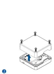
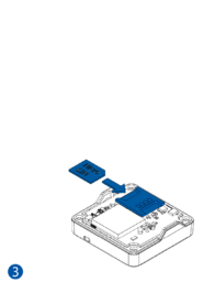
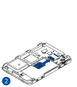
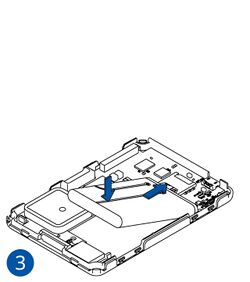
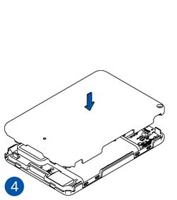
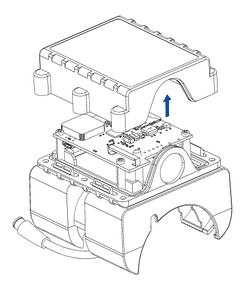
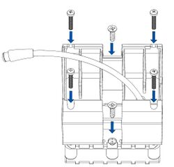
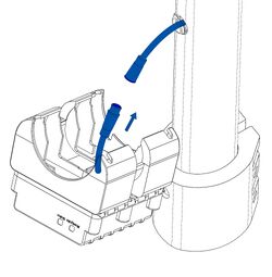
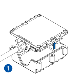
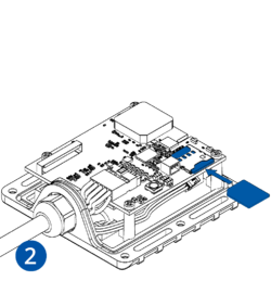
- Look for your device in the device list below and find the related pictures.
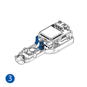
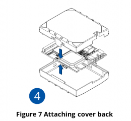
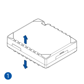
- Carefully remove the device cover - use a pry tool if needed.
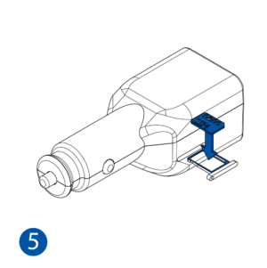
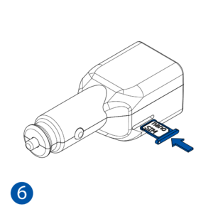
- Some devices have an external SIM card slot. In these cases, first open the slot.
- Insert the SIM card into the SIM card slot. Orient the SIM card correctly - align the cut-off corner.
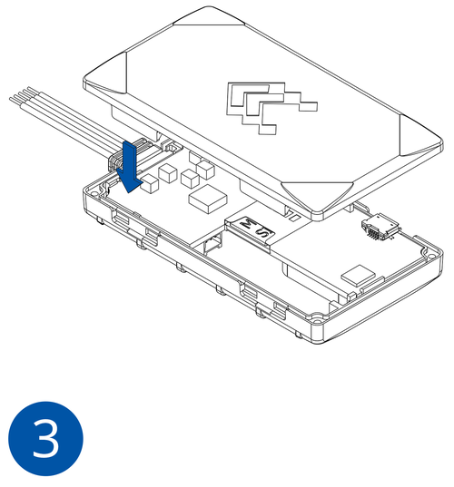
- Connect the battery. Position the battery so that it does not mechanically interfere with other internal components when the cover is closed.
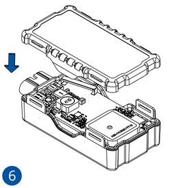
- Some devices require battery cable management and precise steps to insert the internal components back into the enclosure.
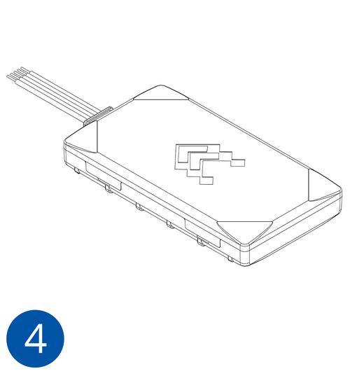
- Re-install the device cover.
The device is now ready to be connected to the PC.
Illustrations to help you prepare the device:
Advanced trackers
STEP 2: Connect the Device to PC
Result: The device is powered with a power supply and connected to the PC.
Requirements for this step:
- Prepared Teltonika Telematics device
- Personal computer with Windows OS, internet connection and:
- COM port drivers (download .zip file here)
- A power supply unit capable of supplying 10-30 VDC.
One of the ways to control your device is by connecting it to a PC via USB or Bluetooth®. Before connecting, power must be provided to the device by a power supply.
For device-specific information about connecting to PC, see Wiki Knowledge Base → Your device model → First Start → PC Connection (Windows).
To connect the device to the PC:
- Install COM port drivers.
- Before connecting the device to the power supply and turning the power supply on, make sure that the power supply will provide voltage in the range of 10-30 VDC, e.g. 12 VDC.
- Do not turn on the power supply. Connect the device to the power supply using the provided power cable.
- Some devices can be powered and configured using only a USB cable, without the need for a separate power supply (in this case, skip to the last step).
- Now, turn on the power supply – device LEDs should start blinking (see LED Status).
- Connect the device to the PC via the provided USB cable or Bluetooth®.
The device is now powered and connected to the PC.
STEP 3: Configure the Device
Result: The device is configured to generate and send records to a specified server.
Requirements for this step:
- Teltonika Telematics device connected to the PC
- PC with Windows OS and latest Microsoft .NET Framework.
- Teltonika Configurator software (download the latest version here).
Every Teltonika Telematics device is pre-configured with default factory settings. Use the Teltonika Configurator software and easily change device settings to meet your specific needs.
Here, we go through the most important features of the Configurator:
- Starting the Configurator.
- Using the most important menus: Status, System, GPRS, and Data Acquisition.
Start the Configurator
On your PC, start the Configurator and select your connected device.
The primary window opens. It contains three areas:
- Top area - loading and saving configurations, updating firmware, and other actions.
- Left-side area - shows menus containing various device settings. Each device may have a different set of settings.
- Main area - here, the settings will show up when you click on a menu.
| Important! | After making changes to the configuration, save them by clicking “Save to device.”To restore the configuration to default factory settings, click “Reset configuration”.
To disconnect from the device, click the device button (top right). |
Status Menu
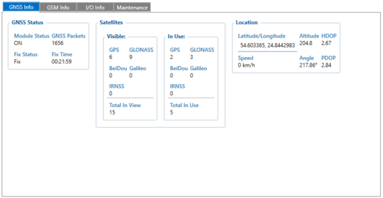
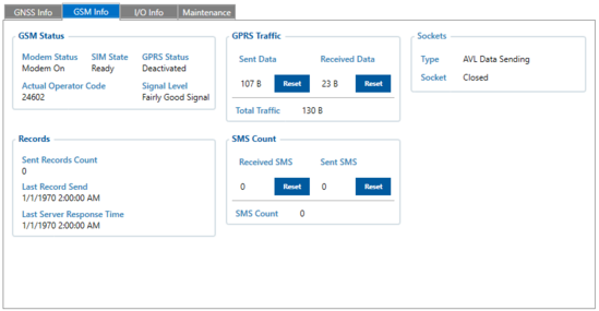
The Status menu contains general device information. View statuses of the main systems, such as GNSS and GSM, in separate tabs.
| Tab in Status menu | Description | Most important parameters to watch |
|---|---|---|
| GNSS info | Shows status of GNSS module and the fix status, counts for packets and satellites, location information. | Module Status – shows whether the GNSS module is ON or in one of the Sleep modes. |
| Fix Status – shows if a satellite fix is available.
Make sure that the device is facing an open sky - at least four visible satellites are required for a GNSS fix. | ||
| GSM info | Shows GSM modem and SIM status, signal level, record sending timestamps, GPRS traffic and SIM data, sockets. | Signal Level – shows the signal level.
Make sure that signal is available – this allows the device to successfully send data to the server. |
| Type – shows the type of GPRS connection. | ||
| Socket – shows socket information (“Closed”, or the server domain and port used to send AVL data via TCP/UDP). | ||
| I/O info | Shows current values from all configurable I/O elements. | |
| Maintenance | Allows capturing data logs, accelerometer data, and calibrating LLS sensors. | |
System Menu
The System menu contains global settings that control the general operation of the tracking device.
GPRS Menu
The GPRS menu allows configuring server and GPRS settings.
With a correct GPRS/server setting configuration, the device will synchronize time, and update records to the configured server. The device will do this based on time intervals set in the Data Acquisition menu (see below).
| Note! | If you have not yet set up a GNSS tracking service, you can use Teltonika TCP/UDP listener (to receive data from the device) and Teltonika parser (to parse the received information). Download the software here (archive password: 1234). |
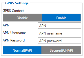
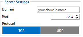
The table below describes the most important parameters in the GPRS menu. This is the minimal required configuration for a device to start sending data to your server.
| Figure | Area | Parameter ID | Parameter description |
|---|---|---|---|
|
GPRS Settings | 2001 | APN (Access Point Name) – a gateway between mobile operator and the public internet.
The device connects to the internet when current APN settings are entered. Obtain the APN from your SIM card provider. Some devices support the Auto APN feature, see here for more information. |
| 2002 | APN username (leave the field empty if there is no APN username). | ||
| 2003 | APN password (leave the field empty if there is no APN password). | ||
|
Server Settings | 2004 | Domain/IP address of destination server. |
| 2005 | Port of destination server. | ||
| 2006 | Protocol for sending data to the destination server (0 – TCP, 1 - UDP). |
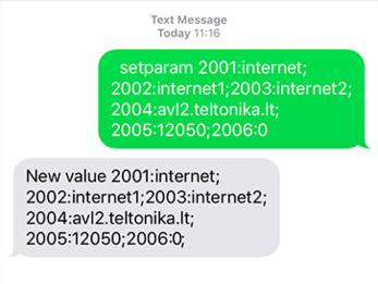
You can also quickly set up your device GPRS settings via SMS. Send the following SMS command. The highlighted parameter IDs are explained in the table above. Make sure to insert two space symbols before SMS text:
" setparam 2001:APN;2002:APN_username;2003:APN_password;2004:Domain;2005:Port;2006:0"
Data Acquisition Menu
The Data Acquisition menu allows configuring how the device acquires data based on the operator type and movement source.
The device will generate periodic records and send them to the server based on the Data Acquisition settings. The default device configuration has optimal parameters pre-configured for best track quality and data usage.
For testing purposes, set certain parameters according to the table below. As can be seen, here we configure the device to make records every 30 seconds and send them also every 30 seconds. The device will switch operating modes (between “On Stop” and “Moving”) based on the status of configured movement source.
After testing, configure Data Acquisition settings according to your needs. For more detailed information about configuring your device using the Teltonika Configurator, see Wiki Knowledge Base → Your device model → Configuration.
The table below describes the most important parameters in the Data Acquisition menu.
STEP 4: Mount the Device
Result: The device is mounted in an optimal location, with good GNSS and GSM connectivity.
Requirements for this step:
- Teltonika Telematics device with a basic configuration
- The tracked object (vehicle, asset) (if available)
Every Teltonika Telematics device has specific mounting instructions. Some devices are plug-and-play, while hard-wired devices require professional installation.
For detailed information about wiring your specific device, see Wiki Knowledge Base → Your device model → First Start → Mounting recommendations and precautions.
The most important mounting recommendations are:
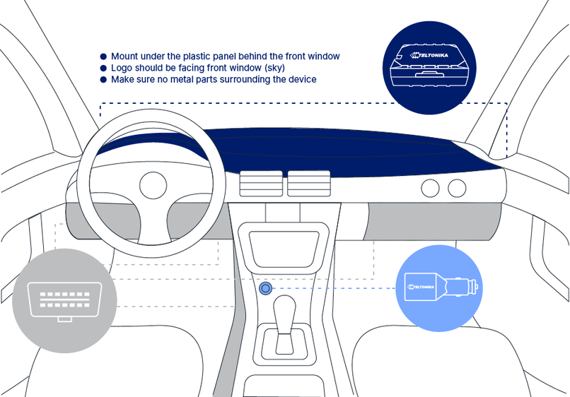
- For vehicles, if possible, mount the device under the plastic panel behind the front window.
- The Teltonika logo on the device should be facing the sky – this orients the antennas of the device for best signal reception.
- Make sure that no metal parts surround the device – metal may negatively impact signal reception.
Below is an example illustration for mounting a device.
STEP 5: Track the Device
Result: The user tracks their device on a tracking platform.
Requirements for this step:
- Teltonika Telematics device with a basic configuration
- A user account on one of the supported tracking platforms, or
- Access to a router and a TCP/UDP listener
The last step in basic testing is to get data from your device to a tracking platform.
Do this by using pre-made tracking platforms (see here), or simple TCP/UDP listeners.
To set up a simple TCP/UDP listener on your personal computer:
- Open a TCP/UDP port (see here).
- Do the steps according to Java Parser First Start Guide.
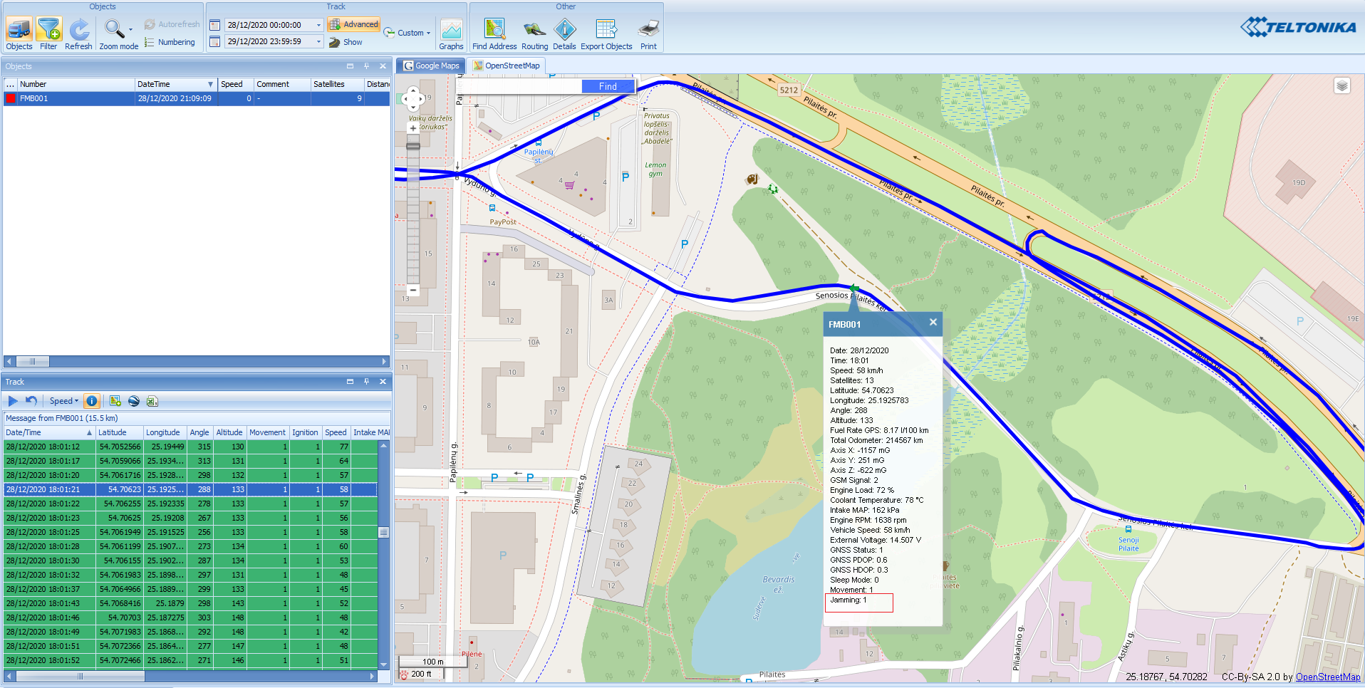
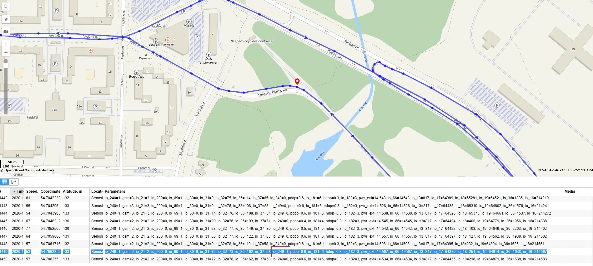
The illustrations below show a device track on different pre-made tracking platforms.
Advanced Testing
Here, we review certain advanced functionalities that allow you to get the most out of your Teltonika Telematics device.
This advanced testing guide is only an example – available functionalities allow accomplishing much more!
Parameter IDs and Advanced SMS capabilities
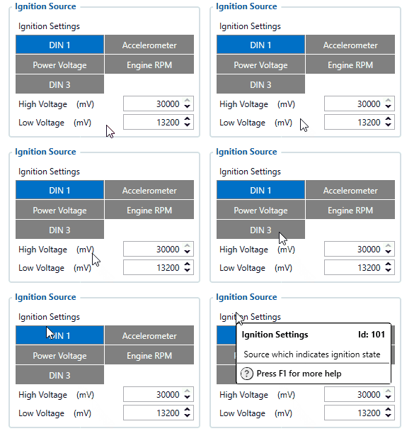
All of the parameters mentioned in the guide above (and many more) have a name and an ID (unique identifier). The parameter ID consists of 3 or 5 digits. See a detailed list of parameters and their IDs here. You can also find a relevant parameter ID by hovering your mouse pointer over a specific parameter in the Configurator.
Parameters of Teltonika Telematics devices may be configured and read via SMS.
Teltonika Telematics devices offer a wide range of SMS configuration and debugging features - see the full list of SMS commands here.
SMS command length is limited to 160 characters.
The general SMS command structure is:
<SMS_Login><space><SMS_Password><space><Command><space>[Parameter ID]:[New Parameter Value];[Parameter ID]:[New Parameter Value]...
- A space symbol separates these elements: SMS login, password, command name, the first parameter:value pair
- A colon symbol separates the parameter ID and the new parameter value
- Multiple parameter values can be changed with one SMS command – a semicolon symbol separates parameter:value pairs.
If no login name and password are set in the device configuration, just omit them in the SMS command. I.e., the command should start with two spaces, followed by the command name.
As an example, let us take one of the most widely used SMS commands: “setparam”. It changes a parameter value, e.g.:
- If a login and password are set:
<SMS_Login><space><SMS_Password><space>setparam<space>101:1
This SMS command will change the parameter “101” (Ignition settings) to “1” (DIN1).
- If no login and password are set:
<space><space>setparam<space>101:2;138:1
This SMS command will change the parameter “101” (Ignition settings) to “2” (Accelerometer) and parameter “138” (Movement source) to “1” (Ignition).
Advanced Use Cases
Beyond basic configuration, Teltonika Telematics devices can be configured as intricately as you require. Most devices can cover a broad spectrum of use cases, while others are highly specialized.
General and specific use cases are presented in the links below. Each category explains what parameters must be configured and why. Where applicable, we provide examples of what information would be available on your server and how to read it.
- General use cases are presented on the Teltonika Telematics website here.
- Specific technical usage scenarios are presented on the Telematics Wiki here.
Solutions
Here, we overview Teltonika Telematics solutions to remotely access, manage and control devices, including external devices, such as tachographs.
FOTA WEB
FOTA WEB is a SaaS solution for the remote, OTA (over-the-air) management of Teltonika Telematics devices.
FOTA WEB allows you to:
- Access your devices through a Web browser on any device
- Upgrade device firmware
- Change the configuration
- Remotely debug FMx devices
- Update CAN adapters without a dedicated application
- Upload a CAN configuration to some devices
For more information, see here.
FOTA WEB is compatible with all currently sold products and is available for all direct Teltonika Telematics customers. Contact Teltonika Telematics sales representatives to obtain access to FOTA WEB. FOTA WEB meets all GDPR requirements.
| Note! | A desktop solution – FOTA – is a predecessor to FOTA WEB. It is mainly used to update EOL (end-of-life) devices. We strongly recommend to use the newest version of FOTA WEB to perform OTA management. |
WEB Tacho
WEB Tacho is an online service that allows to download tachograph files from supported tachographs (using Teltonika Telematics Professional trackers).
The files are first stored on a server, in defined formats (.DDD, .V1B, .C1B, .TGD). The files then can be obtained in various ways: downloaded directly to a PC or to a pre-defined FTP server, or sent to e-mail.
For more information, see here.
Contact Teltonika Telematics sales representatives to obtain access to WEB Tacho.
Protocols
Here, we introduce the communication protocols used by Teltonika Telematics devices.
All Teltonika Telematics devices communicate with servers using specialized protocols, called “codecs”. Each protocol has a particular structure and application scenario. E.g., Codec 8 Extended is used for one-way device to server data transmission, while Codec 12 is used for two-way device-server communication via GPRS messages.
More general information about the various protocols can be found here.


