Teltonika OBD devices are able to read data from heavy duty vehicles. With the OBD to FMS adapter, clients are able to connect OBD devices to their heavy duty vehicles which have FMS female connector (usually located under the front panel). Cable is only applicable with the European truck.
When the RTK option is enabled, the device always tries to use RTK sources first and falls back to internal GNSS if needed.
'''Source priority'''
'''DISCLAIMER:''' ''PLEASE MAKE SURE THE FMS PINOUT OF YOUR HEAVY DUTY VEHICLE IS AS REFERRED ON THE PROVIDED PINOUT SCHEME. IN CASE OF INCORRECT PINOUT PLEASE CONTACT YOUR HEAVY DUTY VEHICLE DEALERSHIP. THE CLIENT IS RESPONSIBLE FOR ALL THE ISSUES, WHICH MIGHT OCCUR BY INCORRECT INSTALLATION.''
#'''RS232 (primary RTK source)'''
#:*The device checks whether any COM port (COM1 or COM2) is configured in RTK mode.
#:*If at least one COM port is configured for RTK and valid data is present, coordinates are taken from RS232.
#'''CAN RTK (secondary RTK source)'''
#:*If RS232 RTK data is not available or is invalid, the device checks the CAN RTK status.
#:*If valid CAN RTK data is available, coordinates are taken from CAN.
#:*A timing check is applied if the time difference between received CAN RTK frames is greater than 2 seconds. The device automatically switches to the internal GNSS receiver (GNS) to keep coordinates up to date.
#'''Internal GNSS (GNS) Fallback'''
#:*If neither RS232 nor CAN provide valid RTK data, the device uses the internal GNSS receiver (GNS) for coordinates.
#'''RTK Disabled'''
#:*If the RTK option is disabled, coordinates are always taken from the internal GNSS receiver.
'''RTK data from CAN'''
'''NOTE:''' ''Please use OBD devices with the latest firmware which has implemented J1939 protocol support.''
When CAN is used as the RTK source, the device reads:
==FMS Plug Location==
*'''Latitude'''
Even though the FMS cable is standardized cable – its placement in the vehicle might differ depending on manufacturer and depending on vehicle trim level.
*'''Longitude'''
*'''Altitude'''
*'''Ground speed'''
*'''Course'''
These values are taken from standard CAN messages designed for GNSS/RTK data. Exact PGNs and signal layouts depend on whether external RTK/ECD/ISOBUS system is being used.
These examples identify the most common locations for the FMS plug.
==Configurator Setup==
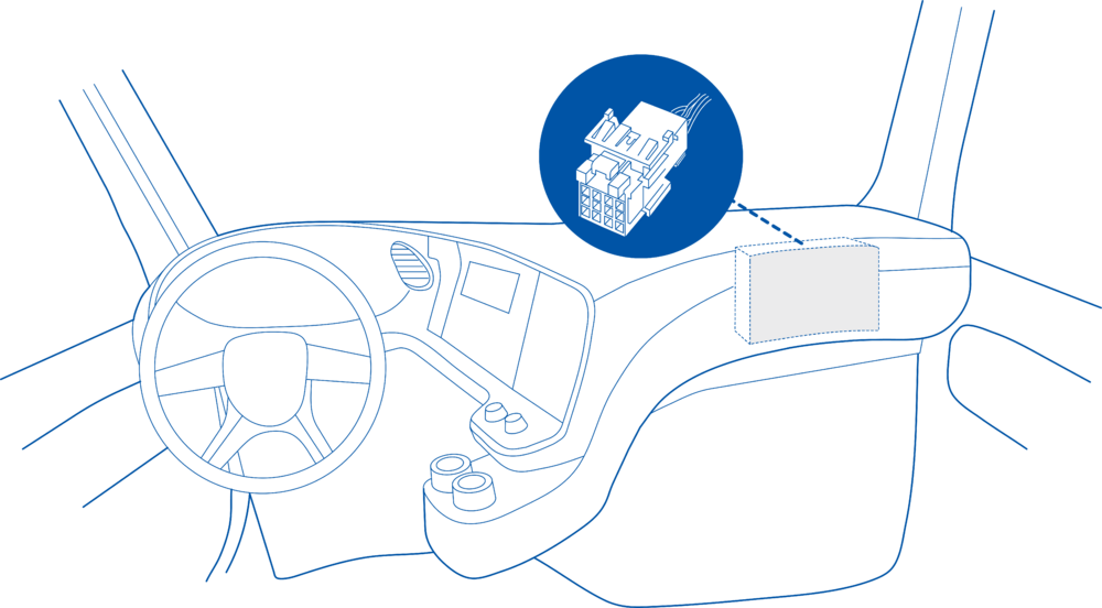
==== Behind the Fuse panel on passenger side – for Example SCANIA S/R/G/P Euro6 Series [[File:Scania R-series 1.3.png|frameless|1000x1000px]] ====
This section describes how to enable RTK as a location source and configure RS232 and CAN usage through the Configurator.
'''Enabling RTK as a location source'''
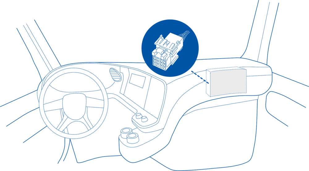
==== Near the Fuse panel on passenger side – for example DAF XF Euro6 [[File:DAF XF 1.3.png|frameless|1000x1000px]] ====
[[File:Source Location from RTK.png|right]]
#Open the Configurator and connect to the FMC650 device.
#Navigate to the System tab.
#Find the option “Source Location from RTK” in the '''System Settings''' section.
#Set this option to '''Enable'''.
When enabled, the device will use RTK data from RS232/CAN if available, with automatic fallback to internal GNSS.
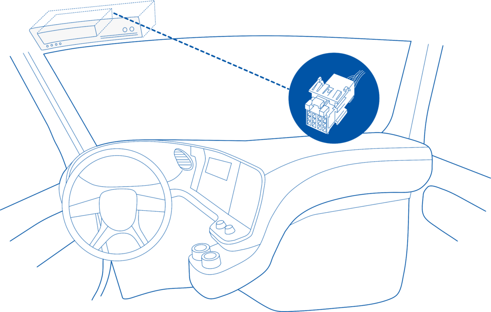
==== Behind the Radio on lower deck – for example Volvo FH Euro5 and Renault T Euro6 [[File:Volvo FH 1.3.png|frameless|1000x1000px]] ====
For advanced configuration (e.g. via commands):
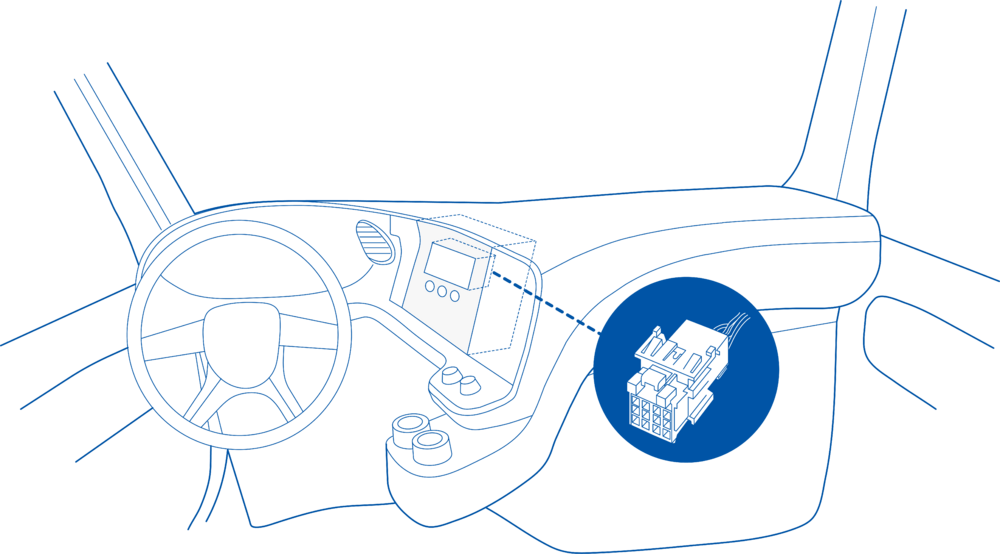
==== Behind the Tachograph on upper deck – for example Mercedes Actros MP5 Euro6 [[File:Mercedes Actros 1.3.png|frameless|1000x1000px]] ====
Source Location from RTK <br>
'''Parameter ID:''' 55000 <br>
'''Values:'''
*'''0''' – Disabled (device uses only internal GNSS)
*'''1''' – Enabled (device uses RTK sources if available)
Configuring RS232 for RTK Use
==Device Configuration==
If you plan to use an external RTK receiver via RS232:
1. Connect your OBD device to PC via USB or Bluetooth.<br>
#Open the RS232/RS485 tab in the Configurator.
2. Open '''Teltonika Configurator''' and find your device in the list.<br>
#For COM1 or COM2 (or both), set the mode to RTK.
3. Select your device from the list.<br>
4. Navigate to '''System''' and under '''System Settings''' Enable '''Codec 8 Extended''' protocol.<br>
5. Open '''OBD II''' section on the left.<br>
6. In '''General''' -> '''OBD II Settings''' -> '''OBD Feature''' select '''ELD'''.<br>
7. In '''OBD VIN settings'''-> '''VIN Source''' select prefered source. Some heavy duty vehicles may not automaticly provide VIN number, in that case we recommend to setup VIN manually.<br>
[[File:OBD II Settings.png|500x500px]]<br>
8. Save the configuration by pressing '''Save to device''' on the top.<br>
9. New section with J1939 parameters can be found in '''ELD''' section on the right bottom.<br>
[[File:ELD Settings.png|500x500px]]<br>
Relevant parameter IDs:
==Supported Parameter List==
*'''COM1 mode''' – Parameter ID 151
*'''COM2 mode''' – Parameter ID 173
*'''RTK mode''' – Value 60
If at least one COM port is configured to RTK mode and valid RTK data is received, the device will use RS232 as the main coordinate source.
[[File:RS232 settings - RTK.png|right]]
The full supported parameter list for OBD devices can be found in the following pages:
*[[FMB001 Teltonika Data Sending Parameters ID]]
*[[FMB003 Teltonika Data Sending Parameters ID]]
*[[FMC003 Teltonika Data Sending Parameters ID]]
*[[FMM003 Teltonika Data Sending Parameters ID]]
*[[FMM00A Teltonika Data Sending Parameters ID]]
'''Using CAN as the RTK Source'''
==Downloads==
CAN-based RTK is used in the following cases:
This functionality requires the latest OBD [[Teltonika Configurator versions|configurator]] and [[Firmware versions#OBD trackers|firmware]] for optimal performance.
*None of the RS232 COM ports are configured in RTK mode, or
*RS232 RTK data is not valid or not present.
When those conditions are met and valid CAN RTK data is received:
*The device uses CAN as the coordinate source.
*The device continuously monitors the time between RTK messages.
*If CAN RTK messages are delayed by more than 2 seconds, the device automatically reverts to internal GNSS to avoid stale coordinates.
<br>
RTK data taken from CAN includes:
*'''Latitude
*'''Longitude
*'''Altitude
*'''Ground speed
*'''Course
Configuration of RTK over CAN (e.g. PGN, source address, bitrate) depends on your external CAN/ISOBUS/RTK infrastructure and should follow that system’sdocumentation.
==Ordering and Specifications==
For more information about '''OBD-II to FMS adapter''' specifications and ordering, please visit [https://www.teltonika-gps.com/products/accessories/data-cables/obd-ii-to-fms-adapter OBD-II TO FMS ADAPTER] web page.
'''ISOBUS Data Visibility'''
When used in ISOBUS or similar environments:
[[File:ISOBUS - RTK.png]]
*RTK-related data from CAN is visible in the ISOBUS section of the Configurator.
*This allows you to verify that RTK data is being received and interpreted correctly by the device.
==Active Location Source Monitoring==
To understand which source is currently being used for position data, you can check the '''Location Source''' parameter.
'''Location Source Values'''
In the Configurator:
#Navigate to the '''I/O''' tab (or equivalent I/O monitoring view).
#Find the parameter '''Location Source'''.
[[File:Location source.png]]
Possible values:
*'''0 – GNS'''
Location is taken from the internal GNSS receiver. This is the default when RTK is disabled or when no valid RTK data is available.
*'''1 – RS232'''
Location is taken from the RTK receiver connected via RS232.
*'''2 – CAN'''
Location is taken from RTK data arriving over CAN.
*'''3 – Err'''
Location is taken from the internal GNSS receiver, but this status indicates that RTK data from RS232 and/or CAN is invalid or unavailable. This helps distinguish normal GNSS use from “RTK expected but not available” situations.
This parameter is used for diagnostics and for confirming that your device is using the intended RTK source.
==NMEA Fix Type Monitoring (RS232 RTK Only)==
When RTK coordinates are received via RS232, you can also monitor the NMEA Fix Type to understand the quality of the GNSS/RTK fix.
'''Configurator Steps'''
#Open the Configurator.
#Go to the I/O tab (or relevant section).
#Locate the parameter '''NMEA Fix Type'''.
[[File:NMEA Fix Type.png]]
'''Note:''' This parameter is '''only available when coordinate data is received via RS232 RTK'''.
'''NMEA Fix Type Values'''
*'''NotValid''' - No valid GNSS fix is available.<br>
*'''GPS''' - Standard GPS fix using satellites only.<br>
Teltonika OBD devices are able to read data from heavy duty vehicles. With the OBD to FMS adapter, clients are able to connect OBD devices to their heavy duty vehicles which have FMS female connector (usually located under the front panel). Cable is only applicable with the European truck.
Cable pinout scheme
Cable pinout scheme:
OBD 16PF
FMS 12PM
4/5
=>
1
6
=>
6
14
=>
9
16
=>
12
DISCLAIMER:PLEASE MAKE SURE THE FMS PINOUT OF YOUR HEAVY DUTY VEHICLE IS AS REFERRED ON THE PROVIDED PINOUT SCHEME. IN CASE OF INCORRECT PINOUT PLEASE CONTACT YOUR HEAVY DUTY VEHICLE DEALERSHIP. THE CLIENT IS RESPONSIBLE FOR ALL THE ISSUES, WHICH MIGHT OCCUR BY INCORRECT INSTALLATION.
NOTE:Please use OBD devices with the latest firmware which has implemented J1939 protocol support.
FMS Plug Location
Even though the FMS cable is standardized cable – its placement in the vehicle might differ depending on manufacturer and depending on vehicle trim level.
These examples identify the most common locations for the FMS plug.
Behind the Fuse panel on passenger side – for Example SCANIA S/R/G/P Euro6 Series
Near the Fuse panel on passenger side – for example DAF XF Euro6
Behind the Radio on lower deck – for example Volvo FH Euro5 and Renault T Euro6
Behind the Tachograph on upper deck – for example Mercedes Actros MP5 Euro6
Device Configuration
1. Connect your OBD device to PC via USB or Bluetooth.
2. Open Teltonika Configurator and find your device in the list.
3. Select your device from the list.
4. Navigate to System and under System Settings Enable Codec 8 Extended protocol.
5. Open OBD II section on the left.
6. In General -> OBD II Settings -> OBD Feature select ELD.
7. In OBD VIN settings-> VIN Source select prefered source. Some heavy duty vehicles may not automaticly provide VIN number, in that case we recommend to setup VIN manually.
8. Save the configuration by pressing Save to device on the top.
9. New section with J1939 parameters can be found in ELD section on the right bottom.
Supported Parameter List
The full supported parameter list for OBD devices can be found in the following pages: