Difference between revisions of "FMT100 First Start"
m (Protected "FMT100 First Start" ([Edit=Allow only administrators] (indefinite) [Move=Allow only administrators] (indefinite))) |
Simkunas.ma (talk | contribs) |
||
| (18 intermediate revisions by 6 users not shown) | |||
| Line 1: | Line 1: | ||
{{Template:FMT1 First start card|model=FMT100}} | {{Template:FMT1 First start card|model=FMT100}} | ||
| − | |||
| − | |||
| + | <font size="+2"><span style=color:#104996>'''FMT100 device pinout'''</span></font> | ||
| − | == | + | {| class="wikitable" |
| − | < | + | |+ |
| − | + | ! style="background: white; color: #F6A83E;" | Pin number | |
| − | + | | style="background: white; color: #F6A83E;" | Pin name | |
| + | | style="background: white; color: #F6A83E;" | Description | ||
| + | |- | ||
| + | | style="text-align: left; background: #F6F6FB;" | 1 | ||
| + | | style="text-align: left; background: #F6F6FB;" | <span style=color:#FF0000>'''VCC'''</span> (10-30)V DC (+) | ||
| + | | style="text-align: left; background: #F6F6FB;" | Power supply (+10-30 V DC). | ||
| + | |- | ||
| + | | style="text-align: left; background: #F6F6FB;" | 2 | ||
| + | | style="text-align: left; background: #F6F6FB;" | <span style=color:#000000>'''GND''' </span>(-) | ||
| + | | style="text-align: left; background: #F6F6FB;" | Ground. | ||
| + | |} | ||
| + | |||
| + | {{Template:FMT1 First start config|model=FMT100|config_link=[[FMT100 Configuration|here]]}} | ||
{{Template:FMT1 Mounting recommendations|model=FMT100|voltage=+10..+30}} | {{Template:FMT1 Mounting recommendations|model=FMT100|voltage=+10..+30}} | ||
| − | https://teltonika | + | https://teltonika.lt/product/fmt100/ |
| − | |||
| − | |||
Revision as of 07:27, 12 June 2018
Main Page > Fast & Easy Trackers > FMT100 > FMT100 First Start
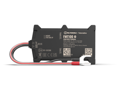
Special and small waterproof GNSS tracker with built-in accelerometer.
Know your device
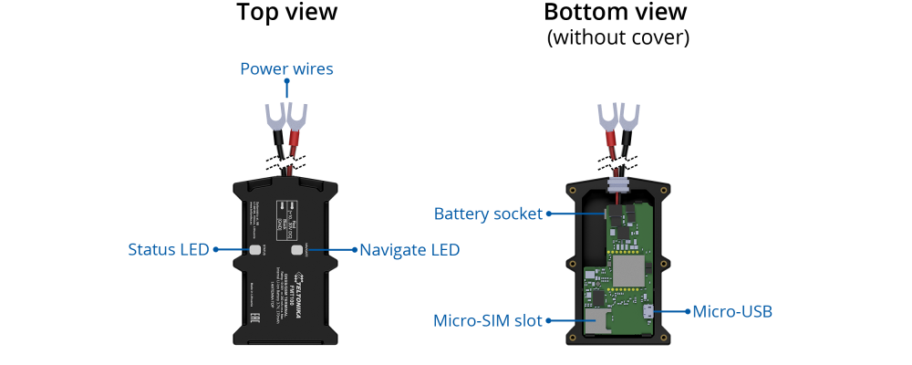
Pinout
| PIN NUMBER | PIN NAME | DESCRIPTION | |
|---|---|---|---|
| 1 | VCC (10-30)V DC (+) | (Red) Power supply (+10-30 V DC) | |
| 2 | GND (-) | (Black) Ground |
Set up your device
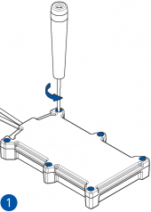
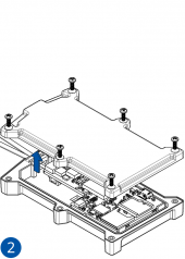
How to insert Micro-SIM card and connect the battery
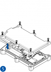
- Unscrew 6 screws counterclockwise.
- Remove the cover.
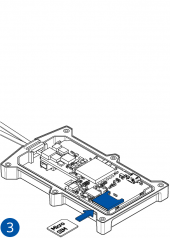
- Insert Micro-SIM card as shown with PIN request disabled or read Security info how to enter it later with Teltonika Configurator. Make sure that Micro-SIM card cut-off corner is pointing forward to slot.
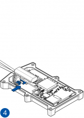
- Connect the battery as shown to device. Position the battery in place where it does not obstruct other components.
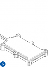
- After configuration, see PC Connection (Windows), attach device cover back and screw in all screws.
- Device is ready to be mounted.
| Micro-SIM card insertion/removal must be performed when device is powered off – external voltage and battery are disconnected. Otherwise Micro-SIM card might be damaged or device will not detect it. |
FMT100 device pinout
| Pin number | Pin name | Description |
|---|---|---|
| 1 | VCC (10-30)V DC (+) | Power supply (+10-30 V DC). |
| 2 | GND (-) | Ground. |
How to install FMT100 drivers (Windows)
1. Please download COM port drivers from Teltonika here.
2. Extract and run TeltonikaCOMDriver.exe. This driver is used to control FMT100 device when it is connected to the computer.
3. Click Next in driver installation window.
4. In the following window click Install button.
5. Setup will continue installing the driver and eventually the confirmation window will appear. Click Finish to complete the setup. You are now ready to use the device on your computer.
Configuration (Windows)
| Operating system | MS .NET Framework version | Version | Links |
|---|---|---|---|
| Windows XP with SP3 or later | MS .NET Framework 4 with KB2468871-v2 update | 32 and 64 bit | https://www.microsoft.com/en-US/Download/confirmation.aspx?id=17718 |
| 32 bit (x86) , 64 bit (x64 or IA64) | https://www.microsoft.com/en-us/download/details.aspx?id=3556
http://avl1.teltonika.lt/downloads/software/Framework/.NET%20Framework%204%20update%20KB2468871-v2/ | ||
| Windows Vista Windows 7 Windows 8.1 Windows 10 |
MS .NET Framework 4.6.2 | 32 and 64 bit | https://www.microsoft.com/en-us/download/confirmation.aspx?id=53344 |
At first FMT100 device will have default factory settings set. These settings should be changed according to the user's needs.
Device can be configured to acquire and send data to server, in this case the GSM settings shall be set in regards with GSM operator's information. If device GSM is unavailable, the device will not be able to send the data and FMT100 will start storing records to flash memory. It is possible to store up to 192000 data records with 128 MB SD memory card (when 100 MB are used to store records). It will send data over GPRS when it is available. Note that FMT100 might reach its full memory capacity. If such case happens, the device will start deleting the oldest records in order to save new ones.
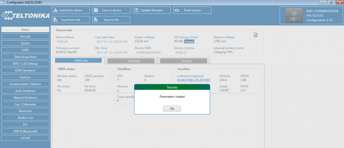
FMT100 configuration is performed via FMT100 Configurator program. Contact sales manager to get the latest FMT100 Configurator version or download from https://teltonika.lt/?media_dl=7290. FMT100 configurator operates on Microsoft Windows OS and uses prerequisite MS .NET Framework.
Module configuration can be performed over USB cable or using a Blue-tooth connection. Configuration process begins by starting FMT100 Configurator software and then connecting to FMT100 device via Connect button located in Online menu part. FMT100 has one user editable profile, which can be loaded and saved to the device. After any modification of configuration the changes need to be saved to FMT100 device using Save to device button.
Main buttons offer following functionality:
- Load from device – loads configuration from device.
- Save to device – saves configuration to device.
- Load from file – loads configuration from file.
- Save to file – saves configuration to file.
- Update firmware – updates firmware on device.
- Reset device – sets device configuration to default.
More details on using the Configurator can be found here.
Mounting recommendations
Device fastening
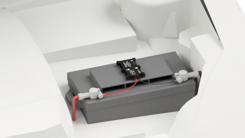
- Locate the battery in your vehicle. If present remove the battery cover to access the battery.
- Wipe clean the installation surface of the battery if any dust or dirt is visable.
- There is a double sided tape on the back of the device, use it to attach the device on the battery, so that the GNSS antenna and LEDs indicators are facing up.
Connecting power wire
- Device power wire is designed to be directly connected to the positive terminal fastener of the vehicle battery.
Connecting ground wire
- Device ground wire is designed to be directly connected to the negative terminal fastener of the vehicle battery.
Safety information
This message contains information on how to operate FMT100 safely. By following these requirements and recommendations, you will avoid any dangerous situations. You must read these instructions carefully and follow them strictly before operating the device!
- The device uses a 10 V...30 V DC power supply. The nominal voltage is 12 V DC. The allowed range of voltage is 10 V...30 V DC.
- To avoid mechanical damage, it is advised to transport the device in an impact-proof package.
- Before dismounting the device from the vehicle, ignition MUST be OFF.

