Difference between revisions of "FMB120 First Start"
From Wiki Knowledge Base | Teltonika GPS
Atabasnikov (talk | contribs) m |
|||
| (78 intermediate revisions by 18 users not shown) | |||
| Line 1: | Line 1: | ||
| − | + | [[Image:Qsg_rut950_teltonika.PNG|centre]] | |
| − | |||
| − | |||
| − | |||
| − | |||
| − | |||
| − | |||
| − | |||
| − | |||
| − | |||
| − | |||
| − | |||
| − | |||
| − | |||
| − | |||
| − | |||
| − | |||
| − | |||
| − | |||
| + | <b><font size="+10">FMB120 GNSS/GSM/Bluetooth tracker with internal GNSS/GSM antennas and internal battery</font></b> | ||
| + | |||
| + | <font size="+3">Quick Start Guide</font> [[Image:Fmb120 man.png|600px|right]] | ||
| + | |||
| + | |||
| + | |||
| + | |||
| + | |||
| + | |||
| + | |||
| + | |||
| + | |||
| + | |||
| + | |||
| + | |||
| + | |||
| + | |||
| + | |||
| + | |||
| + | |||
| + | |||
| + | |||
| + | |||
| + | |||
| + | |||
| + | |||
| + | |||
| + | |||
| + | |||
| + | |||
| + | <font size="+3"><span style=color:#104996>'''How to insert micro SIM card into FMB120'''</span></font> | ||
| + | |||
| + | <font size="+2"><span style=color:#F49E21> 1. </span> Remove FMB120 cover. </font> | ||
| + | |||
| + | <font size="+2"><span style=color:#F49E21> 2. </span> Insert SIM card as shown. SIM slot 1 is closer to PCB, SIM slot 2 is the upper one. </font> | ||
| + | |||
| + | <font size="+2"><span style=color:#F49E21> 3. </span> Attach cover. </font> | ||
| + | |||
| + | <font size="+2"><span style=color:#F49E21> 4. </span> Device is ready. </font> | ||
| + | |||
| + | |||
| + | |||
| + | [[Image:Fmb120_cover_1.png|600px|left]] [[Image:Fmb120_cover_3.png|600px]] | ||
| + | |||
| + | |||
| + | |||
| + | [[Image:Fmb120_cover_2.png|600px|left]] [[Image:Fmb120_cover_4.png|600px]] | ||
| + | |||
| + | |||
| + | |||
| + | <font size="+3"><span style=color:#104996>'''2x6 socket pinout'''</span></font> | ||
| + | [[Image:Fmb_120_2x6_pinout.png|200px|right]] | ||
{| class="wikitable" | {| class="wikitable" | ||
|+ | |+ | ||
| − | ! style=" | + | ! style="background: white; color: #F6A83E;" | Pin number |
| − | + | | style="background: white; color: #F6A83E;" | Pin name | |
| − | + | | style="background: white; color: #F6A83E;" | Description | |
| − | | | + | |- |
| + | | style="text-align: left; background: #F6F6FB;" | 1 | ||
| + | | style="text-align: left; background: #F6F6FB;" | VCC (10-30)V DC (+) | ||
| + | | style="text-align: left; background: #F6F6FB;" | Power supply (10-30 V DC). | ||
|- | |- | ||
| − | | style=" | + | | style="text-align: left; background: #F6F6FB;" | 2 |
| − | | style=" | + | | style="text-align: left; background: #F6F6FB;" | AIN 1 |
| − | | style=" | + | | style="text-align: left; background: #F6F6FB;" | Analog input, channel 1. Input range: 0-30V DC. |
|- | |- | ||
| − | | style=" | + | | style="text-align: left; background: #F6F6FB;" | 3 |
| − | | style=" | + | | style="text-align: left; background: #F6F6FB;" | AIN 2 / DIN 3 |
| − | | style=" | + | | style="text-align: left; background: #F6F6FB;" | Analog input, channel 2. Input range: 0-30V DC / Digital input, channel 3. |
|- | |- | ||
| − | | style=" | + | | style="text-align: left; background: #F6F6FB;" | 4 |
| − | | style=" | + | | style="text-align: left; background: #F6F6FB;" | DIN 2 |
| − | | style=" | + | | style="text-align: left; background: #F6F6FB;" | Digital input, channel 2. |
|- | |- | ||
| − | | style=" | + | | style="text-align: left; background: #F6F6FB;" | 5 |
| − | | style=" | + | | style="text-align: left; background: #F6F6FB;" | DIN 1 |
| − | | style=" | + | | style="text-align: left; background: #F6F6FB;" | Digital input, channel 1. |
|- | |- | ||
| − | | style=" | + | | style="text-align: left; background: #F6F6FB;" | 6 |
| − | | style=" | + | | style="text-align: left; background: #F6F6FB;" | INPUT 6 |
| − | | style=" | + | | style="text-align: left; background: #F6F6FB;" | TX EXT (LVCAN – TX). |
|- | |- | ||
| − | | style=" | + | | style="text-align: left; background: #F6F6FB;" | 7 |
| − | | style=" | + | | style="text-align: left; background: #F6F6FB;" | GND (-) |
| − | | style=" | + | | style="text-align: left; background: #F6F6FB;" | Ground. |
|- | |- | ||
| − | | style=" | + | | style="text-align: left; background: #F6F6FB;" | 8 |
| − | | style=" | + | | style="text-align: left; background: #F6F6FB;" | OUT 1 |
| − | | style=" | + | | style="text-align: left; background: #F6F6FB;" | Digital output, channel 1. Open collector output. Max. 3,3 A DC. |
|- | |- | ||
| − | | style=" | + | | style="text-align: left; background: #F6F6FB;" | 9 |
| − | + | | style="text-align: left; background: #F6F6FB;" | OUT 2 | |
| − | + | | style="text-align: left; background: #F6F6FB;" | Digital output, channel 2. Open collector output. Max. 3,3 A DC. | |
| − | |||
| − | | style=" | ||
| − | |||
| − | | style=" | ||
|- | |- | ||
| − | | style=" | + | | style="text-align: left; background: #F6F6FB;" | 10 |
| − | | style=" | + | | style="text-align: left; background: #F6F6FB;" | 1WIRE POWER |
| − | | style=" | + | | style="text-align: left; background: #F6F6FB;" | +3,8 V output for 1–Wire devices. |
|- | |- | ||
| − | | style=" | + | | style="text-align: left; background: #F6F6FB;" | 11 |
| − | | style=" | + | | style="text-align: left; background: #F6F6FB;" | 1WIRE DATA |
| − | | style=" | + | | style="text-align: left; background: #F6F6FB;" | Data for 1–Wire devices. |
|- | |- | ||
| − | | style=" | + | | style="text-align: left; background: #F6F6FB;" | 12 |
| − | | style=" | + | | style="text-align: left; background: #F6F6FB;" | INPUT 5 |
| − | | style=" | + | | style="text-align: left; background: #F6F6FB;" | RX EXT (LVCAN - RX). |
|- | |- | ||
|} | |} | ||
| − | |||
| − | |||
| − | |||
| − | |||
| − | |||
| − | |||
| − | |||
| − | |||
| − | |||
| − | |||
| − | |||
| − | |||
| − | |||
| − | |||
| − | |||
| − | |||
| − | |||
| − | |||
| − | |||
| − | |||
| − | |||
| − | |||
| − | |||
| − | |||
| − | |||
| − | |||
| − | |||
| − | + | ||
| + | |||
| + | |||
| + | |||
| + | |||
| + | |||
| + | |||
| + | |||
| + | |||
| + | https://teltonika.lt/product/fmb120-internal-gnss-antenna-battery/ | ||
Revision as of 09:01, 10 April 2018
Main Page > Advanced Trackers > FMB120 > FMB120 First Start
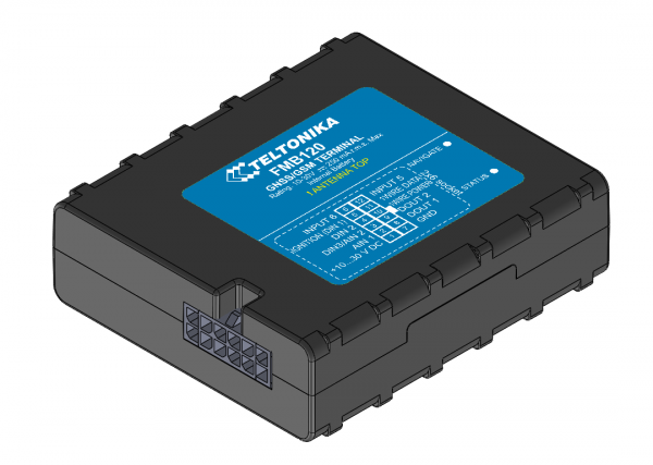
FMB120 GNSS/GSM/Bluetooth tracker with internal GNSS/GSM antennas and internal battery
Quick Start Guide
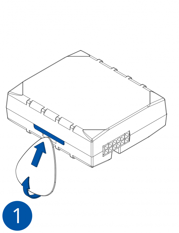
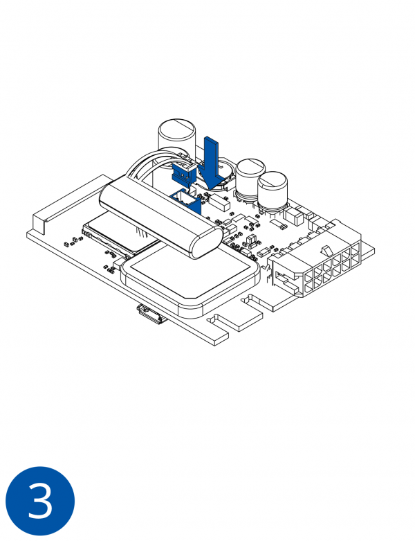
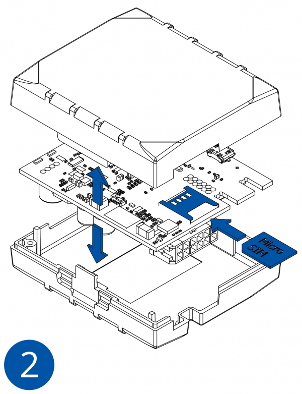
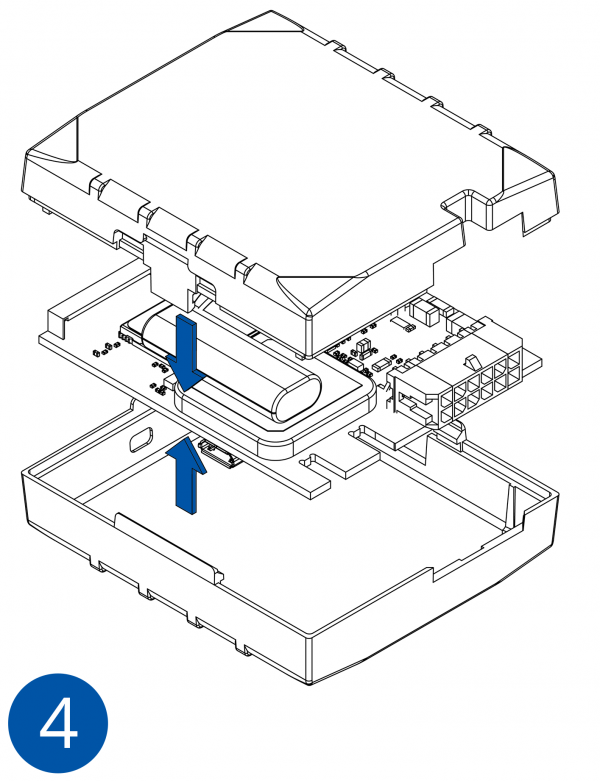
How to insert micro SIM card into FMB120
1. Remove FMB120 cover.
2. Insert SIM card as shown. SIM slot 1 is closer to PCB, SIM slot 2 is the upper one.
3. Attach cover.
4. Device is ready.
2x6 socket pinout
| Pin number | Pin name | Description |
|---|---|---|
| 1 | VCC (10-30)V DC (+) | Power supply (10-30 V DC). |
| 2 | AIN 1 | Analog input, channel 1. Input range: 0-30V DC. |
| 3 | AIN 2 / DIN 3 | Analog input, channel 2. Input range: 0-30V DC / Digital input, channel 3. |
| 4 | DIN 2 | Digital input, channel 2. |
| 5 | DIN 1 | Digital input, channel 1. |
| 6 | INPUT 6 | TX EXT (LVCAN – TX). |
| 7 | GND (-) | Ground. |
| 8 | OUT 1 | Digital output, channel 1. Open collector output. Max. 3,3 A DC. |
| 9 | OUT 2 | Digital output, channel 2. Open collector output. Max. 3,3 A DC. |
| 10 | 1WIRE POWER | +3,8 V output for 1–Wire devices. |
| 11 | 1WIRE DATA | Data for 1–Wire devices. |
| 12 | INPUT 5 | RX EXT (LVCAN - RX). |
https://teltonika.lt/product/fmb120-internal-gnss-antenna-battery/

