|
|
| (16 intermediate revisions by the same user not shown) |
| Line 1: |
Line 1: |
| | <b>{{{description|Small and smart tracker}}}</b> | | <b>{{{description|Small and smart tracker}}}</b> |
| − | {{{pic|[[Image:FTC921-QJABO-datasheet-2023-09-25.1.png|400px|right]]}}} | + | {{{pic|[[Image:FTC921.png|400px|right]]}}} |
| − | <br>
| |
| − | <br>
| |
| | <br> | | <br> |
| | + | |
| | __TOC__ | | __TOC__ |
| | | | |
| − | =='''KNOW YOUR DEVICE'''==
| |
| − | [[File:FTC921_KNOW_YOUR_DEVICE.png|centre|1000 px]]
| |
| | | | |
| − | =='''HOW TO INSERT NANO-SIM CARD AND CONNECT THE BATTERY'''== | + | =='''HOW TO INSERT MICRO-SIM CARD AND CONNECT THE BATTERY'''== |
| | | | |
| | {{{with_battery| | | {{{with_battery| |
| Line 28: |
Line 25: |
| | | | |
| | =='''PC CONNECTION (WINDOWS)'''== | | =='''PC CONNECTION (WINDOWS)'''== |
| − | # Power- up FTC921 with DC voltage (10-90V) power supply using power wires. LEDs should start blinking, see “'''[[FTC921_LED_behaviour_description|LED behaviour description]]'''”.
| + | 1. Power- up FTC921 with DC voltage (10-90V) power supply using power wires. LEDs should start blinking. |
| − | # Connect device to computer using USB Type-C cable and install USB driver, see "[[#How to install USB drivers (Windows)|'''HOW TO INSTALL USB DRIVERS (WINDOWS)''']]".
| + | |
| | + | 2. Connect device to computer using USB Type-C cable and install USB driver, see “How to install USB drivers (Windows)1” |
| | | | |
| | =='''HOW TO INSTALL USB DRIVERS (WINDOWS)'''== | | =='''HOW TO INSTALL USB DRIVERS (WINDOWS)'''== |
| | + | 1. Please download COM port drivers from [https://wiki.teltonika-gps.com/images/d/d0/TeltonikaCOMDriver.zip here]. |
| | + | |
| | + | 2. Extract and run TeltonikaCOMDriver.exe. |
| | + | |
| | + | 3. Click Next in driver installation window. |
| | | | |
| − | # Please download COM port drivers from '''[[Media:TeltonikaCOMDriver.zip|here]]'''.
| + | 4. In the following window click Install button. |
| − | # Extract and run '''TeltonikaCOMDriver.exe'''.
| + | |
| − | # Click '''Next''' in driver installation window.
| + | 5. Setup will continue installing the driver and eventually the confirmation window will appear. Click Finish to complete the |
| − | # In the following window click '''Install''' button.
| + | setup. |
| − | # Setup will continue installing the driver and eventually the confirmation window will appear. Click '''Finish''' to complete the setup.
| |
| | | | |
| | =='''CONFIGURATION (WINDOWS)'''== | | =='''CONFIGURATION (WINDOWS)'''== |
| Line 44: |
Line 46: |
| | configuration can be performed via [https://wiki.teltonika-gps.com/view/Telematics_Configuration_Tool_(TCT) Teltonika Configurator tool (TCT)]. | | configuration can be performed via [https://wiki.teltonika-gps.com/view/Telematics_Configuration_Tool_(TCT) Teltonika Configurator tool (TCT)]. |
| | | | |
| − | =='''PINOUT'''== | + | =='''MOUNTING RECOMMENDATIONS'''== |
| − | | + | '''DEVICE FASTENING''' |
| − | {| class="wikitable"
| |
| − | |+
| |
| − | ! style="width:5%; border: 1px solid white; border-bottom: 2px solid #0054A6; background: white; color: #0054A6; text-align: left;"| PIN NUMBER
| |
| − | ! style="width:5%; border: 1px solid white; border-bottom: 2px solid #0054A6; background: white; color: #0054A6; text-align: left;"| PIN NAME
| |
| − | ! style="width:20 px; border: 1px solid white; border-bottom: 2px solid #0054A6; background: white; color: #0054A6; text-align: left;"|
| |
| − | DESCRIPTION
| |
| − | | rowspan="13" style="border: 1px solid white; border-bottom: 2px solid #E8E8E8; text-align: left; vertical-align: center; background: white;" |[[Image:FTC921_PINOUT.png|400px|center]]
| |
| − | |-
| |
| − | |-
| |
| − | | style="border: 1px solid white; border-bottom: 2px solid #E8E8E8;lenght: 50 px; text-align: left; vertical-align: center; background: white;" | 1
| |
| − | | style="border: 1px solid white; border-bottom: 2px solid #E8E8E8; text-align: left; vertical-align: center; background: white;" | <span style=color:#FF0000>'''VCC'''</span>
| |
| − | | style="border: 1px solid white; border-bottom: 2px solid #E8E8E8; text-align: left; vertical-align: center; background: white;" | (Red) Power supply (+10-90 V DC) (+).
| |
| − | |-
| |
| − | | style="border: 1px solid white; border-bottom: 2px solid #E8E8E8; text-align: left; vertical-align: center; background: white;" | 2
| |
| − | | style="border: 1px solid white; border-bottom: 2px solid #E8E8E8; text-align: left; vertical-align: center; background: white;" | <span style=color:#000000>'''GND''' </span>
| |
| − | | style="border: 1px solid white; border-bottom: 2px solid #E8E8E8; text-align: left; vertical-align: center; background: white;" | (Black) Ground (-).
| |
| − | |-
| |
| − | | style="border: 1px solid white; border-bottom: 2px solid #E8E8E8; text-align: left; vertical-align: center; background: white;" | 3
| |
| − | | style="border: 1px solid white; border-bottom: 2px solid #E8E8E8; text-align: left; vertical-align: center; background: white;" | <span style=color:#FFEF00>'''DIN1'''</span>
| |
| − | | style="border: 1px solid white; border-bottom: 2px solid #E8E8E8; text-align: left; vertical-align: center; background: white;" | (Yellow) Digital input, channel 1. DEDICATED FOR IGNITION INPUT. Input range: 7.5-90 V DC.
| |
| − | |-
| |
| − | | style="border: 1px solid white; border-bottom: 2px solid #E8E8E8; text-align: left; vertical-align: center; background: white;" | 4
| |
| − | | style="border: 1px solid white; border-bottom: 2px solid #E8E8E8; text-align: left; vertical-align: center; background: white;" | <span style=color:#3B3B3B>'''AIN1'''</span>
| |
| − | | style="border: 1px solid white; border-bottom: 2px solid #E8E8E8; text-align: left; vertical-align: center; background: white;" | (Grey) Analog input, channel 1. Input range: 0-90 V DC.
| |
| − | |-
| |
| − | | style="border: 1px solid white; border-bottom: 2px solid #E8E8E8; text-align: left; vertical-align: center; background: white;" | 5
| |
| − | | style="border: 1px solid white; border-bottom: 2px solid #E8E8E8; text-align: left; vertical-align: center; background: white;" | <span style=color:#E0E0E0>'''DOUT1'''</span>
| |
| − | | style="border: 1px solid white; border-bottom: 2px solid #E8E8E8; text-align: left; vertical-align: center; background: white;" | (White) Digital output. Open collector output. Max. 0,5 A DC.
| |
| − | |-
| |
| − | |}
| |
| | | | |
| − | =='''MOUNTING RECOMMENDATIONS'''==
| + | • Locate the battery in your vehicle. If present remove the battery cover to access the battery. |
| − | '''CONNECTING WIRES'''
| |
| | | | |
| − | * Wires should be fastened to stable wires or other non-moving parts. Any heat emitting and/or moving objects should be kept away from the wires.<br />
| + | • There is a double sided tape on the back of the device, use it to attach the device on the battery, so that the GNSS antenna |
| − | * There should be no exposed wires. If factory isolation was removed while connecting wires, the isolation material should be applied.<br />
| + | and LEDs indicators are facing up. |
| − | * If the wires are placed in the exterior or in places where they can be damaged or exposed to heat, humidity, dirt, etc., additional isolation should be <br />applied and the wires should not be loose.<br />
| |
| − | * Wires cannot be connected to the board computers or control units.<br />
| |
| | | | |
| | '''CONNECTING POWER SOURCE''' | | '''CONNECTING POWER SOURCE''' |
| | | | |
| − | * Be sure that after the car computer goes to sleep mode, power might be still available on the power wires. Depending on car, this may happen in 5 to 30 minutes period.<br />
| + | • Device power wire is designed to be directly connected to the positive terminal fastener of the vehicle battery. |
| − | * When module is connected, measure voltage again to make sure it did not decrease.<br />
| |
| − | * It is recommended to connect to the main power cable in the fuse box.<br />
| |
| − | * 3 A, 125 V external fuse shall be used.<br />
| |
| | | | |
| | '''CONNECTING GROUND WIRE''' | | '''CONNECTING GROUND WIRE''' |
| | | | |
| − | * Ground wire is connected to the vehicle frame or metal parts that are fixed to the frame.<br />
| + | • Connect ground wire to the vehicle frame or metal parts that are fixed to the frame. |
| − | * If the wire is fixed with the bolt, the loop must be connected to the end of the wire.<br />
| + | |
| − | * For better contact scrub paint from the spot where loop is going to be connected.<br />
| + | • If the wire is fixed with the bolt, the loop must be connected to the end of the wire. |
| | + | |
| | + | • Device ground wire is designed to be directly connected to the negative terminal fastener of the vehicle battery. |
| | | | |
| | [[Category:FTC921]] | | [[Category:FTC921]] |
Small and smart tracker
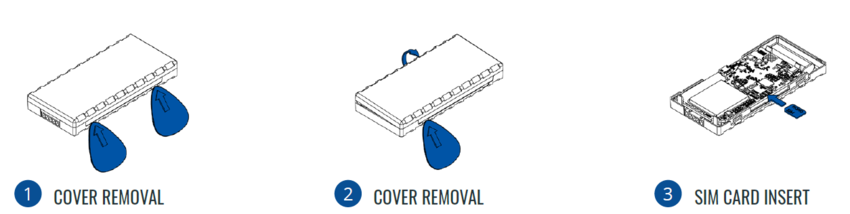
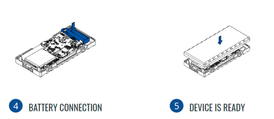
HOW TO INSERT MICRO-SIM CARD AND CONNECT THE BATTERY
- Gently remove FTC921 cover using plastic pry tool from one side.
- Gently remove FTC921 cover using plastic pry tool from another side.
- Insert Nano-SIM card as shown. Make sure that Nano-SIM card cut-off corner is pointing forward to slot.
- Connect the battery as shown on device. Position the battery in place where it does not obstruct other components.
- Attach device cover back. Device is ready to be connected.
|
Nano-SIM card insertion/removal must be performed when device is powered off – external voltage and internal battery disconnected. Otherwise Nano-SIM card might be damaged or device will not detect it.
|
PC CONNECTION (WINDOWS)
1. Power- up FTC921 with DC voltage (10-90V) power supply using power wires. LEDs should start blinking.
2. Connect device to computer using USB Type-C cable and install USB driver, see “How to install USB drivers (Windows)1”
HOW TO INSTALL USB DRIVERS (WINDOWS)
1. Please download COM port drivers from here.
2. Extract and run TeltonikaCOMDriver.exe.
3. Click Next in driver installation window.
4. In the following window click Install button.
5. Setup will continue installing the driver and eventually the confirmation window will appear. Click Finish to complete the
setup.
CONFIGURATION (WINDOWS)
At first FTC921 device will have default factory settings set. These settings should be changed according to the user's needs. Main
configuration can be performed via Teltonika Configurator tool (TCT).
MOUNTING RECOMMENDATIONS
DEVICE FASTENING
• Locate the battery in your vehicle. If present remove the battery cover to access the battery.
• There is a double sided tape on the back of the device, use it to attach the device on the battery, so that the GNSS antenna
and LEDs indicators are facing up.
CONNECTING POWER SOURCE
• Device power wire is designed to be directly connected to the positive terminal fastener of the vehicle battery.
CONNECTING GROUND WIRE
• Connect ground wire to the vehicle frame or metal parts that are fixed to the frame.
• If the wire is fixed with the bolt, the loop must be connected to the end of the wire.
• Device ground wire is designed to be directly connected to the negative terminal fastener of the vehicle battery.


