Difference between revisions of "FTC881 First Start"
From Wiki Knowledge Base | Teltonika GPS
| (21 intermediate revisions by 2 users not shown) | |||
| Line 1: | Line 1: | ||
| − | <b>{{{description|Small and smart tracker}}}</b> | + | <b>{{{description|Small and smart waterproof tracker}}}</b> |
| − | {{{pic|[[Image:FTC881.png|400px|right]]}}} | + | {{{pic|[[Image:FTC881-QJABO-datasheet-2023-09-25.1.png|400px|right]]}}} |
<br> | <br> | ||
__TOC__ | __TOC__ | ||
| + | =='''KNOW YOUR DEVICE'''== | ||
| + | [[File:FTC881 KNOW YOUR DEVICE.PNG|centre|1000 px]] | ||
| − | =='''HOW TO INSERT | + | =='''HOW TO INSERT NANO-SIM CARD'''== |
{{{with_battery| | {{{with_battery| | ||
| − | # | + | # Device is delivered partly closed. Gently remove {{{model|FTC881}}} '''cover'''. |
| − | + | # Insert '''{{{sim_type|Nano-}}}SIM''' card as shown. Make sure that {{{sim_type|Nano-}}}SIM card '''cut-off corner''' is pointing towards SIM slot. | |
| − | # Insert '''{{{sim_type|Nano-}}}SIM''' card as shown. Make sure that {{{sim_type|Nano-}}}SIM card '''cut-off corner''' is pointing | + | # Battery is already connected, so after configuring device fully close casing. |
| − | # | + | # Device is ready to be mounted.}}} |
| − | # | ||
| − | {{{SIM1|[[Image: | + | {{{SIM1|[[Image:FTX8_device_setup.png|850px]]}}} |
| − | |||
| Line 24: | Line 24: | ||
|} | |} | ||
| − | ==''' | + | =='''HOW TO REMOVE COVER'''== |
| − | |||
| − | + | {| | |
| + | |- | ||
| + | | [[File:Alert.png|left|link=]] || <b> Device casing is designed to be water-proof and match requirements for IP69K. Please note that once the cover is fully clipped it will require additional plastic pry tools to be opened! Please make sure to review short walkthrough video for more details:</b> | ||
| + | |} | ||
| + | <youtube>https://www.youtube.com/watch?v=fgOQtk6X0nw</youtube> | ||
| + | =='''PC CONNECTION (WINDOWS)'''== | ||
| + | # Power- up FTC881 with DC voltage (10-90V) power supply using power wires. LEDs should start blinking, see “'''[[FTC881_LED_behaviour_description|LED behaviour description]]'''”. | ||
| + | # Connect device to computer using USB Type-C cable and install USB driver, see "[[#How to install USB drivers (Windows)|'''HOW TO INSTALL USB DRIVERS (WINDOWS)''']]". | ||
=='''HOW TO INSTALL USB DRIVERS (WINDOWS)'''== | =='''HOW TO INSTALL USB DRIVERS (WINDOWS)'''== | ||
| − | |||
| − | + | # Please download COM port drivers from '''[[Media:TeltonikaCOMDriver.zip|here]]'''. | |
| − | + | # Extract and run '''TeltonikaCOMDriver.exe'''. | |
| − | + | # Click '''Next''' in driver installation window. | |
| − | + | # In the following window click '''Install''' button. | |
| − | + | # Setup will continue installing the driver and eventually the confirmation window will appear. Click '''Finish''' to complete the setup. | |
| − | |||
| − | |||
| − | setup. | ||
=='''CONFIGURATION (WINDOWS)'''== | =='''CONFIGURATION (WINDOWS)'''== | ||
| Line 46: | Line 48: | ||
At first FTC881 device will have default factory settings set. These settings should be changed according to the user's needs. Main | At first FTC881 device will have default factory settings set. These settings should be changed according to the user's needs. Main | ||
configuration can be performed via [https://wiki.teltonika-gps.com/view/Telematics_Configuration_Tool_(TCT) Teltonika Configurator tool (TCT)]. | configuration can be performed via [https://wiki.teltonika-gps.com/view/Telematics_Configuration_Tool_(TCT) Teltonika Configurator tool (TCT)]. | ||
| + | |||
| + | =='''PINOUT'''== | ||
| + | |||
| + | {| class="wikitable" | ||
| + | |+ | ||
| + | ! style="width:10%; border: 1px solid white; border-bottom: 2px solid #0054A6; background: white; color: #0054A6; text-align: left;"| PIN NUMBER | ||
| + | ! style="width:10%; border: 1px solid white; border-bottom: 2px solid #0054A6; background: white; color: #0054A6; text-align: left;"| PIN NAME | ||
| + | ! style="width:20 px; border: 1px solid white; border-bottom: 2px solid #0054A6; background: white; color: #0054A6; text-align: left;"| | ||
| + | DESCRIPTION | ||
| + | | rowspan="13" style="border: 1px solid white; border-bottom: 2px solid #E8E8E8; text-align: left; vertical-align: center; background: white;" |[[Image:FTC_881_Pinout_2.png|300px|center]] | ||
| + | |- | ||
| + | |- | ||
| + | | style="border: 1px solid white; border-bottom: 2px solid #E8E8E8;lenght: 50 px; text-align: left; vertical-align: center; background: white;" | 1 | ||
| + | | style="border: 1px solid white; border-bottom: 2px solid #E8E8E8; text-align: left; vertical-align: center; background: white;" | <span style=color:#FF0000>'''VCC'''</span> | ||
| + | | style="border: 1px solid white; border-bottom: 2px solid #E8E8E8; text-align: left; vertical-align: center; background: white;" | (Red) Power supply (+10-90 V DC) (+). | ||
| + | |- | ||
| + | | style="border: 1px solid white; border-bottom: 2px solid #E8E8E8; text-align: left; vertical-align: center; background: white;" | 2 | ||
| + | | style="border: 1px solid white; border-bottom: 2px solid #E8E8E8; text-align: left; vertical-align: center; background: white;" | <span style=color:#000000>'''GND''' </span> | ||
| + | | style="border: 1px solid white; border-bottom: 2px solid #E8E8E8; text-align: left; vertical-align: center; background: white;" | (Black) Ground (-). | ||
| + | |- | ||
| + | |} | ||
=='''MOUNTING RECOMMENDATIONS'''== | =='''MOUNTING RECOMMENDATIONS'''== | ||
'''DEVICE FASTENING''' | '''DEVICE FASTENING''' | ||
| − | + | * Locate the battery in your vehicle. If present remove the battery cover to access the battery. | |
| − | + | * There is a double sided tape on the back of the device, use it to attach the device on the battery, so that the GNSS antenna and LEDs indicators are facing up. | |
| − | |||
| − | and LEDs indicators are facing up. | ||
'''CONNECTING POWER SOURCE''' | '''CONNECTING POWER SOURCE''' | ||
| − | + | * Device power wire is designed to be directly connected to the positive terminal fastener of the vehicle battery. | |
'''CONNECTING GROUND WIRE''' | '''CONNECTING GROUND WIRE''' | ||
| − | + | * Device ground wire is designed to be directly connected to the negative terminal fastener of the vehicle battery. | |
| − | |||
| − | |||
| − | |||
| − | |||
[[Category:FTC881]] | [[Category:FTC881]] | ||
Latest revision as of 10:02, 3 June 2024
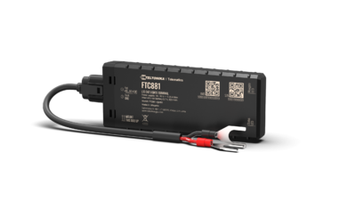
Main Page > Fast & Easy Trackers > FTC881 > FTC881 First StartSmall and smart waterproof tracker
KNOW YOUR DEVICE
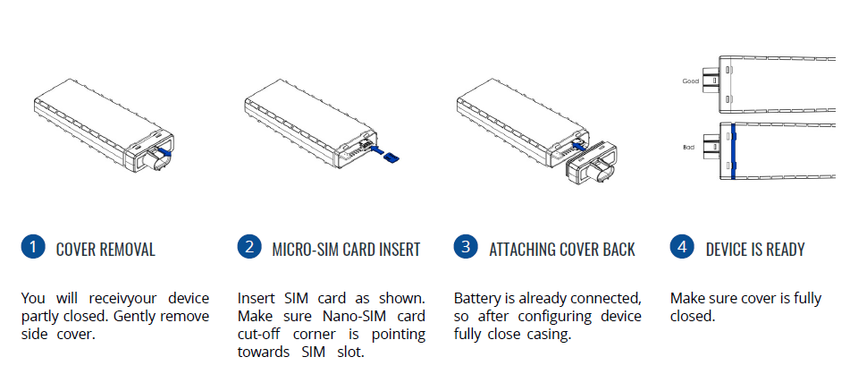
HOW TO INSERT NANO-SIM CARD
- Device is delivered partly closed. Gently remove FTC881 cover.
- Insert Nano-SIM card as shown. Make sure that Nano-SIM card cut-off corner is pointing towards SIM slot.
- Battery is already connected, so after configuring device fully close casing.
- Device is ready to be mounted.
 |
Nano-SIM card insertion/removal must be performed when device is powered off – external voltage and internal battery disconnected. Otherwise Nano-SIM card might be damaged or device will not detect it. |
HOW TO REMOVE COVER
 |
Device casing is designed to be water-proof and match requirements for IP69K. Please note that once the cover is fully clipped it will require additional plastic pry tools to be opened! Please make sure to review short walkthrough video for more details: |
PC CONNECTION (WINDOWS)
- Power- up FTC881 with DC voltage (10-90V) power supply using power wires. LEDs should start blinking, see “LED behaviour description”.
- Connect device to computer using USB Type-C cable and install USB driver, see "HOW TO INSTALL USB DRIVERS (WINDOWS)".
HOW TO INSTALL USB DRIVERS (WINDOWS)
- Please download COM port drivers from here.
- Extract and run TeltonikaCOMDriver.exe.
- Click Next in driver installation window.
- In the following window click Install button.
- Setup will continue installing the driver and eventually the confirmation window will appear. Click Finish to complete the setup.
CONFIGURATION (WINDOWS)
At first FTC881 device will have default factory settings set. These settings should be changed according to the user's needs. Main configuration can be performed via Teltonika Configurator tool (TCT).
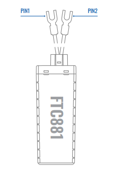
PINOUT
| PIN NUMBER | PIN NAME |
DESCRIPTION |
|
|---|---|---|---|
| 1 | VCC | (Red) Power supply (+10-90 V DC) (+). | |
| 2 | GND | (Black) Ground (-). |
MOUNTING RECOMMENDATIONS
DEVICE FASTENING
- Locate the battery in your vehicle. If present remove the battery cover to access the battery.
- There is a double sided tape on the back of the device, use it to attach the device on the battery, so that the GNSS antenna and LEDs indicators are facing up.
CONNECTING POWER SOURCE
- Device power wire is designed to be directly connected to the positive terminal fastener of the vehicle battery.
CONNECTING GROUND WIRE
- Device ground wire is designed to be directly connected to the negative terminal fastener of the vehicle battery.


