Teltonika OBD devices are able to read data from heavy duty vehicles. With the OBD to FMS adapter, clients are able to connect OBD devices to their heavy duty vehicles which have FMS female connector (usually located under the front panel). Cable is only applicable with the European truck.
The purpose of Secure Engine Cut Off (SECO) is to bring a vehicle to a stop, in order to prevent unauthorized use. SECO disables the fuel pump, which would prevent the engine from continuing to run and stop the vehicle from being driven. For safety reasons, the system is designed to slow the vehicle down gradually in a controlled manner, ensuring that security measures do not compromise the driver’s or passengers’ safety. It is typically triggered by remote commands (SMS or GPRS) and is used for security or immobilization purposes.
*'''SECO functionality''' should have DOUT control priority higher than '''Immobilizer''' scenario.
===<u>How It Works</u>===
Firstly, in order to safely slow down vehicle the systems toggles the relay, which is connected to fuel pump ('''GNSS Available'''). Secondly, at a safe speed, the system tuns on DOUT permanently in order to stop the vehicle ('''Speed Pulse'''). Last mode is activated in case no GNSS fix is available ('''GNSS Unavailable''').
'''Speed Pulse'''
DOUT control starts when the vehicle speed goes below a configured speed threshold and remains below this threshold for a specified speed check period. As soon as that happens DOUT is activated.
The timer will be reset if the vehicle speed increases above the configured speed threshold.
'''GNSS Available'''
This mode requires a GNSS fix to be present before DOUT control begins.
DOUT pulsing starts when the vehicle speed drops below a configured speed pulse threshold and the speed remains below this threshold for a specified speed check period.
'''GNSS Unavailable'''
This mode is used when a GNSS fix is not available.
In this mode, the system initiates DOUT control only if the vehicle is stationary, location data is unavailable, and the movement timeout condition is met.
'''Note:''' If there is no GNSS fix available and “secoon” command is sent, the system waits for the movement timeout to be reached before activating the configured DOUT. This approach ensures that the vehicle is stationary prior to disabling the fuel supply.
<td style="vertical-align: middle; text-align: center;"> Priority of how events are being sent to a server. For example, events with low priority are added to the periodical record, and events with high priority are sent immediately after they occur. </td>
<td style="vertical-align: middle; text-align: left;"> '''0''' = SECO scenario is '''disabled''' <br> '''1''' = SECO scenario is '''low''' <br> '''2''' = SECO scenario is '''high''' <br>
<td style="vertical-align: middle; text-align: center;"> Time span during which speed must be lower than configured for output to activate (GNSS on). </td>
<td style="vertical-align: middle; text-align: left;"> Minimum value = '''0'''<br> Maximum value = '''65535''' <br>Default value = '''10''' </td>
<td style="vertical-align: middle; text-align: center;"> Duration after which the DOUT will be activated if no movement is detected and GNSS is off. </td>
<td style="vertical-align: middle; text-align: left;"> Minimum value = '''0'''<br> Maximum value = '''65535''' <br>Default value = '''30''' </td>
<td style="vertical-align: middle; text-align: center;">Enables feature status sending only when the event happens (an eventual record). When disabled, feature status will be sent with both eventual and periodical records.</td>
<td style="vertical-align: middle; text-align: left;"> '''0''' = SECO status will be sent with both eventual and periodical records. <br> '''1''' = SECO status will be sent only when the event happens (an eventual record).</td>
<td style="vertical-align: middle; text-align: center;">Pulse functionality adds additional output control which helps to slow down vehicle before fully disabling fuel pump.</td>
<td style="vertical-align: middle; text-align: center;"> A value in milliseconds, for how long DOUT should be inactive. </td>
<td style="vertical-align: middle; text-align: left;"> Minimum value = '''10'''<br> Maximum value = '''5000''' <br>Default value = '''1000''' </td>
</tr>
</table>
<!---For Template:FTX SMS/GPRS Commands--->
{{#if: {{FTX Pin Support List|model={{{model}}}|pin=DOUT1}}{{FTX Pin Support List|model={{{model}}}|pin=DOUT2}}{{FTX Pin Support List|model={{{model}}}|pin=DOUT3}}
*Server or Domain address, either IP address or Domain can be written.
'''Port'''
*Server Port.
'''Data protocol'''
*TCP (Transmission control protocol) or UDP (User datagram protocol). Changing this parameter will alter how the device communicates. From the device side, TCP and UDP work almost the same, the only difference is that UDP doesn't need additional confirmation from the server side, that the data packet was received. TCP has that and uses more network data for the confirmation. The desired data transfer protocol can be selected through the configurator. For more information on the protocol differences of Teltonika devices, refer here [https://wiki.teltonika-gps.com/view/Teltonika_Data_Sending_Protocols]
----
'''New description added''' <br>
<span style="color:#00FF00;">'''Encryption'''
*TLS/DTLS are security protocols that protect information sent over a network by encrypting the data so only the intended recipient can read it. These Protocols help authenticate devices communicating with the server and ensure data integrity during transmission. TLS/DTLS encryption creates a secure, private connection so sensitive data can travel safely across networks.</span>
*Tp use TLS/DTLS encryption, server certificates must be uploaded via '''Teltonika Configurator Tool (TCT)''' or '''FOTA Web''' using '''Upload user TLS certificate''' task. For more information, refer to [[{{{model}}} Device status]].
*'''Note:''' Encryption is supported only for TCP/UDP data protocols. MQTT over TLS is not supported in the current implementation.
----
===Secondary server settings===
'''Mode'''
*Backup - Records are sent to second server while main server is not available.
*Duplicate - records are sent to both servers (main and second), records are deleted from Flash storage only if both servers confirmed that the records were received from device.
{| class="wikitable"
{| class="wikitable"
|+ Secondary server parameters
|+'''Cable pinout scheme:'''
!'''OBD 16PF'''
!
!'''FMS 12PM'''
|-
|-
! Parameter !! Parameter ID !! Values
|4/5
|=>
|1
|-
|-
| Second server type || 2010 || 0 - Disable, 1 - Backup, 2 - Duplicate
|6
|=>
|6
|-
|-
| Secondary server IP or DNS address || 2007 || String
'''DISCLAIMER:''' ''PLEASE MAKE SURE THE FMS PINOUT OF YOUR HEAVY DUTY VEHICLE IS AS REFERRED ON THE PROVIDED PINOUT SCHEME. IN CASE OF INCORRECT PINOUT PLEASE CONTACT YOUR HEAVY DUTY VEHICLE DEALERSHIP. THE CLIENT IS RESPONSIBLE FOR ALL THE ISSUES, WHICH MIGHT OCCUR BY INCORRECT INSTALLATION.''
The Fuel Counter GNSS scenario provides fuel consumption estimation using GNSS-derived distance and user-configured fuel rate. It calculates the amount of fuel used by multiplying traveled distance by the average fuel rate and converting it to appropriate units. It is a software-based alternative when fuel flow sensors are not available.
===<u>How It Works</u>===
'''NOTE:''' ''Please use OBD devices with the latest firmware which has implemented J1939 protocol support.''
The scenario monitors GNSS data and updates fuel usage whenever valid GNSS PVT(Position, Velocity, Time) messages are received and movement is detected. It also supports runtime reconfiguration to keep fuel usage parameters in sync with user changes.
==FMS Plug Location==
Even though the FMS cable is standardized cable – its placement in the vehicle might differ depending on manufacturer and depending on vehicle trim level.
These examples identify the most common locations for the FMS plug.
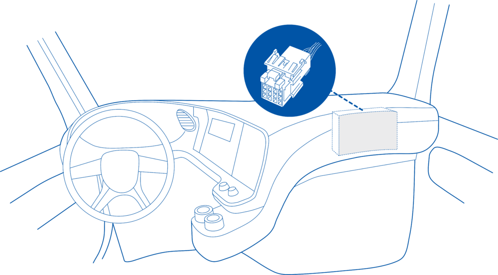
==== Behind the Fuse panel on passenger side – for Example SCANIA S/R/G/P Euro6 Series [[File:Scania R-series 1.3.png|frameless|1000x1000px]] ====
*On device startup, the scenario:
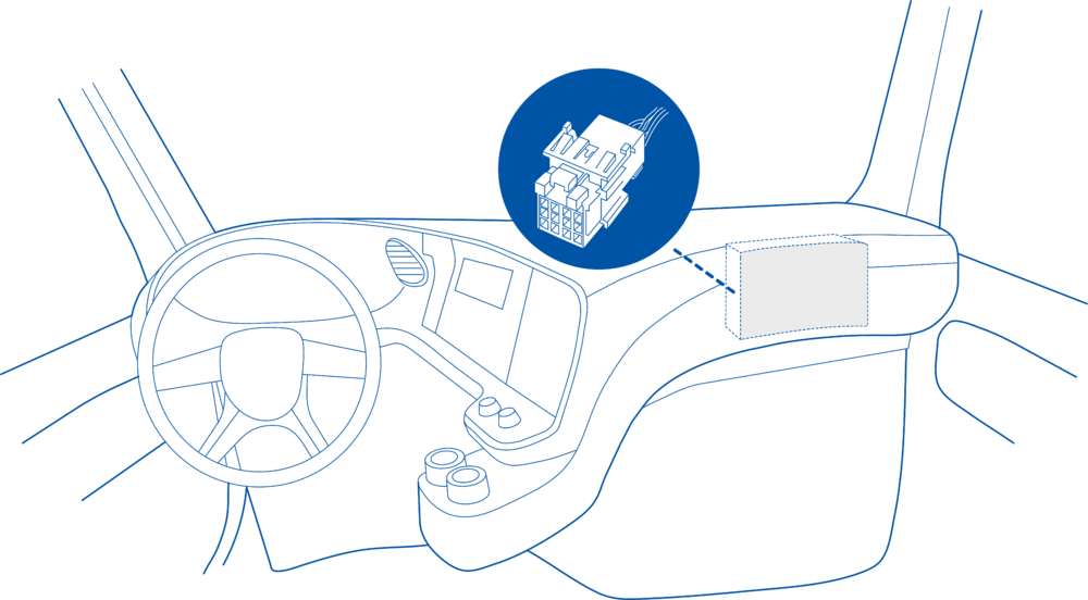
==== Near the Fuse panel on passenger side – for example DAF XF Euro6 [[File:DAF XF 1.3.png|frameless|1000x1000px]] ====
**Checks for a retained value of previously used fuel.
**If found, it restores this value and updates the corresponding I/O element.
**If no retained value is found, the system uses the current configuration parameter (user-defined or default), stores it in retained RAM for future startups, and updates the I/O element.
When GNSS messages are received, the scenario determines whether they represent a GNSS source event or position data, and, if valid movement is detected, updates both distance traveled and fuel consumption.
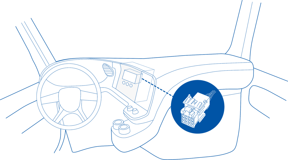
==== Behind the Radio on lower deck – for example Volvo FH Euro5 and Renault T Euro6 [[File:Volvo FH 1.3.png|frameless|1000x1000px]] ====
If the scenario is enabled and the user modifies the average fuel usage parameter, it automatically detects any deviation between the configuration and the current I/O value and synchronizes them.
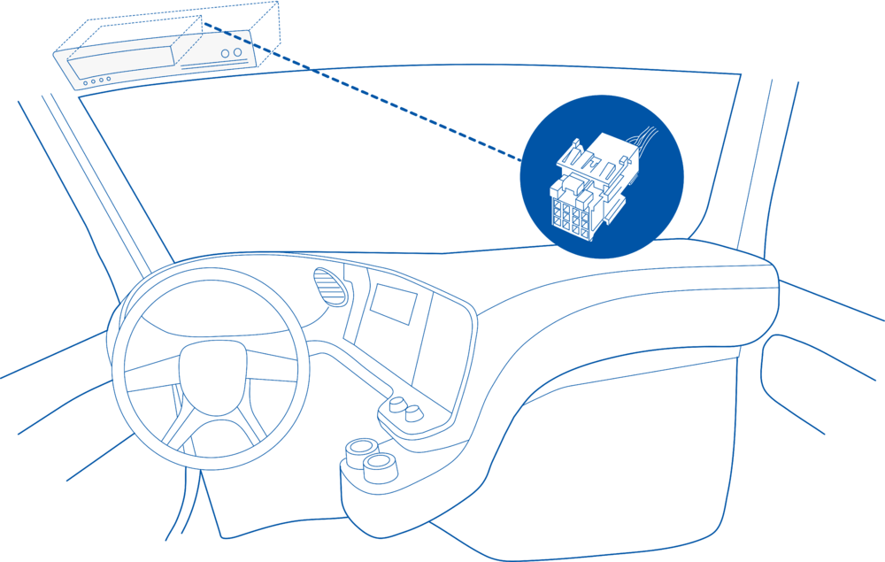
==== Behind the Tachograph on upper deck – for example Mercedes Actros MP5 Euro6 [[File:Mercedes Actros 1.3.png|frameless|1000x1000px]] ====
<td style="vertical-align: middle; text-align: center;">Priority of how events are being sent to a server. For example, events with low priority are added to the periodical record, and events with high priority are sent immediately after they occur.</td>
1. Connect your OBD device to PC via USB or Bluetooth.<br>
2. Open '''Teltonika Configurator''' and find your device in the list.<br>
3. Select your device from the list.<br>
4. Navigate to '''System''' and under '''System Settings''' Enable '''Codec 8 Extended''' protocol.<br>
5. Open '''OBD II''' section on the left.<br>
6. In '''General''' -> '''OBD II Settings''' -> '''OBD Feature''' select '''ELD'''.<br>
7. In '''OBD VIN settings'''-> '''VIN Source''' select prefered source. Some heavy duty vehicles may not automaticly provide VIN number, in that case we recommend to setup VIN manually.<br>
[[File:OBD II Settings.png|500x500px]]<br>
8. Save the configuration by pressing '''Save to device''' on the top.<br>
9. New section with J1939 parameters can be found in '''ELD''' section on the right bottom.<br>
[[File:ELD Settings.png|500x500px]]<br>
<td style="vertical-align: middle; text-align: center;"> Average consumption </td>
This functionality requires the latest OBD [[Teltonika Configurator versions|configurator]] and [[Firmware versions#OBD trackers|firmware]] for optimal performance.
<td style="vertical-align: middle; text-align: center;">The initial fuel counter value in liters. Can be used to set the starting value or reset the current one.</td>
<td style="vertical-align: middle; text-align: left;"> Minimum value = '''0.0'''<br> Maximum value = '''4294967.2''' <br> Default value = '''0.0''' </td>
</tr>
==Ordering and Specifications==
</table>
For more information about '''OBD-II to FMS adapter''' specifications and ordering, please visit [https://www.teltonika-gps.com/products/accessories/data-cables/obd-ii-to-fms-adapter OBD-II TO FMS ADAPTER] web page.
Latest revision as of 09:34, 8 May 2026
Introduction
Teltonika OBD devices are able to read data from heavy duty vehicles. With the OBD to FMS adapter, clients are able to connect OBD devices to their heavy duty vehicles which have FMS female connector (usually located under the front panel). Cable is only applicable with the European truck.
Cable pinout scheme
Cable pinout scheme:
OBD 16PF
FMS 12PM
4/5
=>
1
6
=>
6
14
=>
9
16
=>
12
DISCLAIMER:PLEASE MAKE SURE THE FMS PINOUT OF YOUR HEAVY DUTY VEHICLE IS AS REFERRED ON THE PROVIDED PINOUT SCHEME. IN CASE OF INCORRECT PINOUT PLEASE CONTACT YOUR HEAVY DUTY VEHICLE DEALERSHIP. THE CLIENT IS RESPONSIBLE FOR ALL THE ISSUES, WHICH MIGHT OCCUR BY INCORRECT INSTALLATION.
NOTE:Please use OBD devices with the latest firmware which has implemented J1939 protocol support.
FMS Plug Location
Even though the FMS cable is standardized cable – its placement in the vehicle might differ depending on manufacturer and depending on vehicle trim level.
These examples identify the most common locations for the FMS plug.
Behind the Fuse panel on passenger side – for Example SCANIA S/R/G/P Euro6 Series
Near the Fuse panel on passenger side – for example DAF XF Euro6
Behind the Radio on lower deck – for example Volvo FH Euro5 and Renault T Euro6
Behind the Tachograph on upper deck – for example Mercedes Actros MP5 Euro6
Device Configuration
1. Connect your OBD device to PC via USB or Bluetooth.
2. Open Teltonika Configurator and find your device in the list.
3. Select your device from the list.
4. Navigate to System and under System Settings Enable Codec 8 Extended protocol.
5. Open OBD II section on the left.
6. In General -> OBD II Settings -> OBD Feature select ELD.
7. In OBD VIN settings-> VIN Source select prefered source. Some heavy duty vehicles may not automaticly provide VIN number, in that case we recommend to setup VIN manually.
8. Save the configuration by pressing Save to device on the top.
9. New section with J1939 parameters can be found in ELD section on the right bottom.
Supported Parameter List
The full supported parameter list for OBD devices can be found in the following pages: