Teltonika OBD devices are able to read data from heavy duty vehicles. With the OBD to FMS adapter, clients are able to connect OBD devices to their heavy duty vehicles which have FMS female connector (usually located under the front panel). Cable is only applicable with the European truck.
'''Secure Engine Cut Off (SECO)''' is a functionality that safely disables a vehicle’s engine based on predefined speed or movement conditions. It is typically activated remotely and used for security, immobilization, or theft prevention purposes.
{| class="wikitable"
|+'''Cable pinout scheme:'''
!'''OBD 16PF'''
!
!'''FMS 12PM'''
|-
|4/5
|=>
|1
|-
|6
|=>
|6
|-
|14
|=>
|9
|-
|16
|=>
|12
|}
SECO enhances vehicle security by allowing the engine to be disabled under controlled conditions. It helps prevent theft by stopping unauthorized movement, supports fleet security through remote immobilization when suspicious activity occurs, and limits unauthorized usage by shutting down the engine when vehicles operate outside permitted times or areas.
To safely slow down a vehicle after receiving the <code>secoon</code> command, the device waits for the vehicle speed to drop below the configured '''Speed pulse scenario (km/h)''' threshold. Once the speed remains below this threshold for the configured '''Speed check period''', the device starts pulsing the configured '''DOUT''' to toggle the relay connected to the fuel pump. This intermittently interrupts the fuel supply and gradually slows down the vehicle.
'''DISCLAIMER:''' ''PLEASE MAKE SURE THE FMS PINOUT OF YOUR HEAVY DUTY VEHICLE IS AS REFERRED ON THE PROVIDED PINOUT SCHEME. IN CASE OF INCORRECT PINOUT PLEASE CONTACT YOUR HEAVY DUTY VEHICLE DEALERSHIP. THE CLIENT IS RESPONSIBLE FOR ALL THE ISSUES, WHICH MIGHT OCCUR BY INCORRECT INSTALLATION.''
When the vehicle speed further decreases and reaches the configured '''Speed (km/h)''' threshold, the system activates the configured '''DOUT permanently''', fully interrupting the fuel supply and bringing the vehicle to a complete stop.
'''NOTE:''' ''Please use OBD devices with the latest firmware which has implemented J1939 protocol support.''
DOUT control remains active until the <code>secoff</code> command is received.
==FMS Plug Location==
Even though the FMS cable is standardized cable – its placement in the vehicle might differ depending on manufacturer and depending on vehicle trim level.
===<u>Prerequisites and Important Settings</u>===
These examples identify the most common locations for the FMS plug.
*The device must have at least one free DOUT that can be assigned to SECO functionality.
*For SECO functionality to work, DOUT must be selected. SECO has DOUT control priority higher than immobilizer scenario.
*'''IMOPORTANT:''' If the pulse parameter is disabled while pulsing is active, the DOUT will activate instantly.
*'''IMPORTANT:''' The SECO scenario must be controlled using SMS and GPRS commands, enabling remote activation and deactivation of the engine cut off functionality.
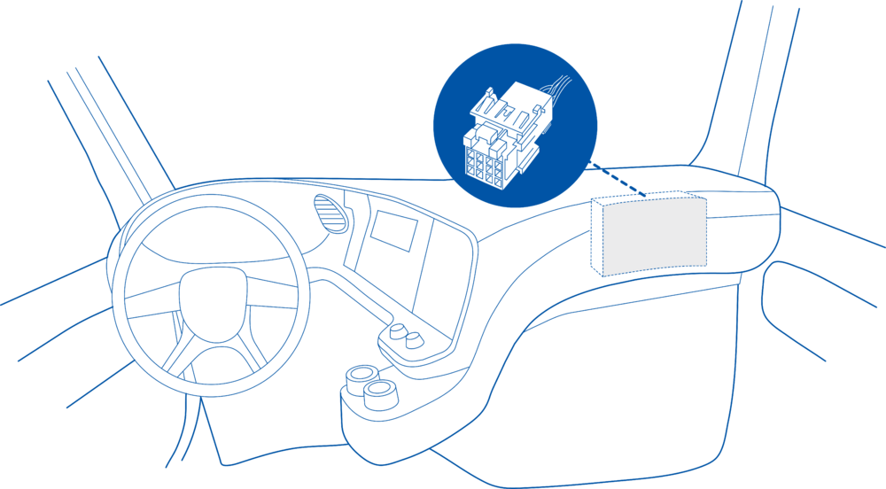
==== Behind the Fuse panel on passenger side – for Example SCANIA S/R/G/P Euro6 Series [[File:Scania R-series 1.3.png|frameless|1000x1000px]] ====
===<u>Basic Operation</u>===
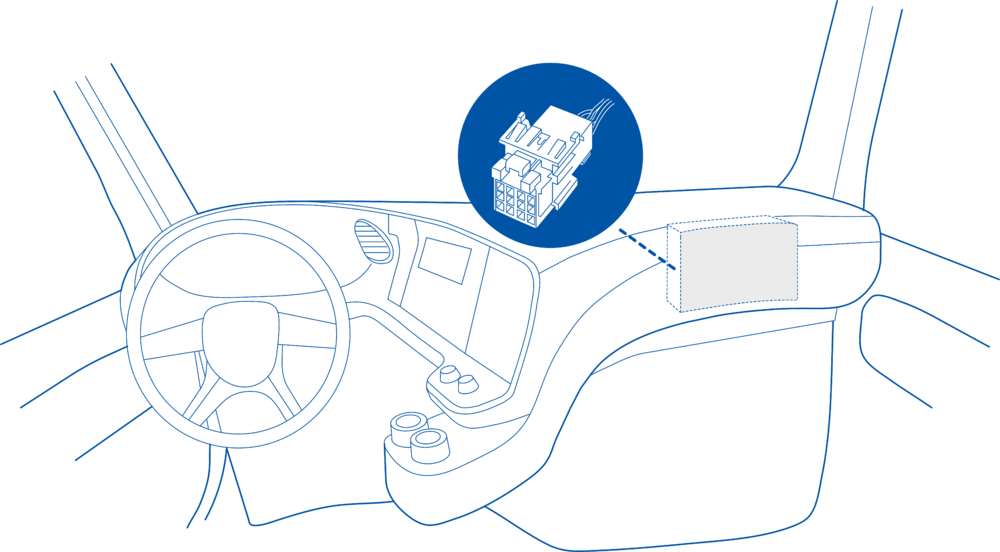
==== Near the Fuse panel on passenger side – for example DAF XF Euro6 [[File:DAF XF 1.3.png|frameless|1000x1000px]] ====
The SECO scenario supports the following engine cut off modes, each using different logic for controlling a digital output (DOUT) based on speed, movement, and data availability.
====Speed Pulse====
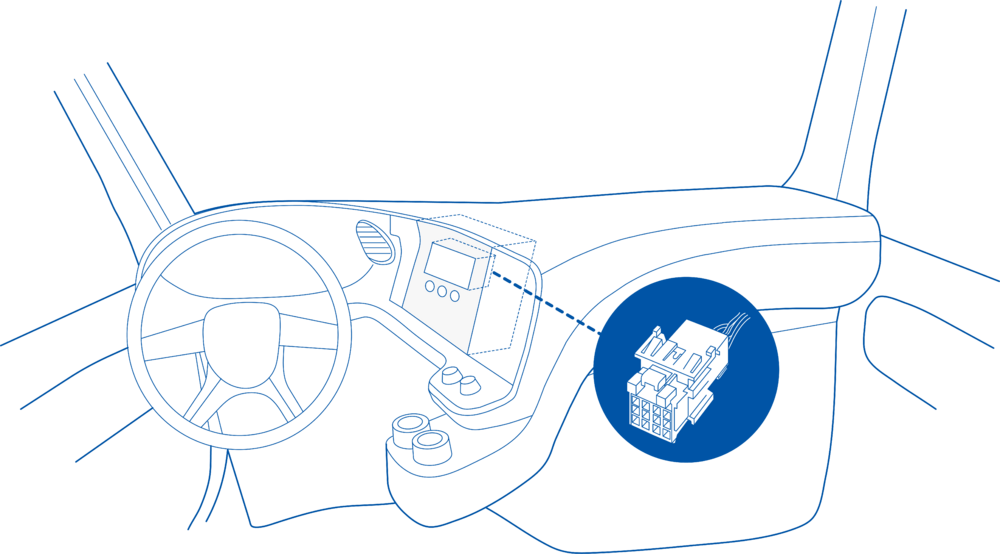
==== Behind the Radio on lower deck – for example Volvo FH Euro5 and Renault T Euro6 [[File:Volvo FH 1.3.png|frameless|1000x1000px]] ====
The Speed pulse scenario (km/h) parameter defines the speed threshold at which pulsed DOUT control begins.
*Speed remains below this threshold for the configured Speed check period
Once these conditions are met, the device begins toggling the configured DOUT according to the DOUT ON duration and DOUT OFF duration settings.
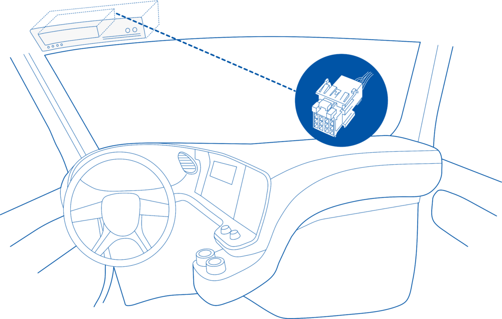
==== Behind the Tachograph on upper deck – for example Mercedes Actros MP5 Euro6 [[File:Mercedes Actros 1.3.png|frameless|1000x1000px]] ====
If the vehicle speed increases above the configured Speed pulse scenario threshold, the Speed check period timer is reset.
====Safe Stop Threshold====
==Device Configuration==
The '''Speed (km/h)''' parameter defines the speed at which the system switches from pulsed control to '''permanent DOUT activation'''.
1. Connect your OBD device to PC via USB or Bluetooth.<br>
2. Open '''Teltonika Configurator''' and find your device in the list.<br>
3. Select your device from the list.<br>
4. Navigate to '''System''' and under '''System Settings''' Enable '''Codec 8 Extended''' protocol.<br>
5. Open '''OBD II''' section on the left.<br>
6. In '''General''' -> '''OBD II Settings''' -> '''OBD Feature''' select '''ELD'''.<br>
7. In '''OBD VIN settings'''-> '''VIN Source''' select prefered source. Some heavy duty vehicles may not automaticly provide VIN number, in that case we recommend to setup VIN manually.<br>
[[File:OBD II Settings.png|500x500px]]<br>
8. Save the configuration by pressing '''Save to device''' on the top.<br>
9. New section with J1939 parameters can be found in '''ELD''' section on the right bottom.<br>
[[File:ELD Settings.png|500x500px]]<br>
When the vehicle speed reaches or falls below this value, the configured '''DOUT''' is activated continuously, completely disabling the fuel pump and stopping the vehicle.
==Supported Parameter List==
====GNSS Available====
The full supported parameter list for OBD devices can be found in the following pages:
When a GNSS fix is available, vehicle speed is determined using GNSS data and the SECO process follows the normal flow:
*[[FMB001 Teltonika Data Sending Parameters ID]]
#Wait until speed drops below '''Speed pulse scenario (km/h)'''
*[[FMB003 Teltonika Data Sending Parameters ID]]
#Start pulsing DOUT after the '''Speed check period'''
*[[FMC003 Teltonika Data Sending Parameters ID]]
#Activate '''DOUT permanently''' when speed reaches '''Speed (km/h)'''
*[[FMM003 Teltonika Data Sending Parameters ID]]
*[[FMM00A Teltonika Data Sending Parameters ID]]
====GNSS Unavailable====
==Downloads==
If a ''''GNSS fix''' is not available, vehicle speed cannot be reliably determined. In this case, the system uses a safety fallback mechanism.
This functionality requires the latest OBD [[Teltonika Configurator versions|configurator]] and [[Firmware versions#OBD trackers|firmware]] for optimal performance.
After receiving the secoon command, the device waits until:
==Ordering and Specifications==
*No movement is detected
For more information about '''OBD-II to FMS adapter''' specifications and ordering, please visit [https://www.teltonika-gps.com/products/accessories/data-cables/obd-ii-to-fms-adapter OBD-II TO FMS ADAPTER] web page.
*The configured Movement timeout is reached
Once these conditions are met, the configured '''DOUT''' is activated.
This ensures that the fuel supply is not interrupted while the vehicle might still be moving at high speed.
<td style="vertical-align: middle; text-align: center;"> Priority of how events are being sent to a server. For example, events with low priority are added to the periodical record, and events with high priority are sent immediately after they occur. </td>
<td style="vertical-align: middle; text-align: left;"> '''0''' = SECO scenario is '''disabled''' <br> '''1''' = SECO scenario is '''low''' <br> '''2''' = SECO scenario is '''high''' <br>
<td style="vertical-align: middle; text-align: center;"> Time span during which speed must be lower than configured for output to activate (GNSS on). </td>
<td style="vertical-align: middle; text-align: left;"> Minimum value = '''0'''<br> Maximum value = '''65535''' <br>Default value = '''10''' </td>
<td style="vertical-align: middle; text-align: center;"> Duration after which the DOUT will be activated if no movement is detected and GNSS is off. </td>
<td style="vertical-align: middle; text-align: left;"> Minimum value = '''0'''<br> Maximum value = '''65535''' <br>Default value = '''30''' </td>
<td style="vertical-align: middle; text-align: center;">Enables feature status sending only when the event happens (an eventual record). When disabled, feature status will be sent with both eventual and periodical records.</td>
<td style="vertical-align: middle; text-align: left;"> '''0''' = SECO status will be sent with both eventual and periodical records. <br> '''1''' = SECO status will be sent only when the event happens (an eventual record).</td>
<td style="vertical-align: middle; text-align: center;">Pulse functionality adds additional output control which helps to slow down vehicle before fully disabling fuel pump.</td>
<td style="vertical-align: middle; text-align: center;"> A value in milliseconds, for how long DOUT should be inactive. </td>
<td style="vertical-align: middle; text-align: left;"> Minimum value = '''10'''<br> Maximum value = '''5000''' <br>Default value = '''1000''' </td>
</tr>
</table>
<!---For Template:FTX SMS/GPRS Commands--->
{{#if: {{FTX Pin Support List|model={{{model}}}|pin=DOUT1}}{{FTX Pin Support List|model={{{model}}}|pin=DOUT2}}{{FTX Pin Support List|model={{{model}}}|pin=DOUT3}}
Teltonika OBD devices are able to read data from heavy duty vehicles. With the OBD to FMS adapter, clients are able to connect OBD devices to their heavy duty vehicles which have FMS female connector (usually located under the front panel). Cable is only applicable with the European truck.
Cable pinout scheme
Cable pinout scheme:
OBD 16PF
FMS 12PM
4/5
=>
1
6
=>
6
14
=>
9
16
=>
12
DISCLAIMER:PLEASE MAKE SURE THE FMS PINOUT OF YOUR HEAVY DUTY VEHICLE IS AS REFERRED ON THE PROVIDED PINOUT SCHEME. IN CASE OF INCORRECT PINOUT PLEASE CONTACT YOUR HEAVY DUTY VEHICLE DEALERSHIP. THE CLIENT IS RESPONSIBLE FOR ALL THE ISSUES, WHICH MIGHT OCCUR BY INCORRECT INSTALLATION.
NOTE:Please use OBD devices with the latest firmware which has implemented J1939 protocol support.
FMS Plug Location
Even though the FMS cable is standardized cable – its placement in the vehicle might differ depending on manufacturer and depending on vehicle trim level.
These examples identify the most common locations for the FMS plug.
Behind the Fuse panel on passenger side – for Example SCANIA S/R/G/P Euro6 Series
Near the Fuse panel on passenger side – for example DAF XF Euro6
Behind the Radio on lower deck – for example Volvo FH Euro5 and Renault T Euro6
Behind the Tachograph on upper deck – for example Mercedes Actros MP5 Euro6
Device Configuration
1. Connect your OBD device to PC via USB or Bluetooth.
2. Open Teltonika Configurator and find your device in the list.
3. Select your device from the list.
4. Navigate to System and under System Settings Enable Codec 8 Extended protocol.
5. Open OBD II section on the left.
6. In General -> OBD II Settings -> OBD Feature select ELD.
7. In OBD VIN settings-> VIN Source select prefered source. Some heavy duty vehicles may not automaticly provide VIN number, in that case we recommend to setup VIN manually.
8. Save the configuration by pressing Save to device on the top.
9. New section with J1939 parameters can be found in ELD section on the right bottom.
Supported Parameter List
The full supported parameter list for OBD devices can be found in the following pages: