Teltonika OBD devices are able to read data from heavy duty vehicles. With the OBD to FMS adapter, clients are able to connect OBD devices to their heavy duty vehicles which have FMS female connector (usually located under the front panel). Cable is only applicable with the European truck.
*Improved internal device watchdog mechanisms to ensure more stable long-term operation.
!
*Fixed inconsistent generation of periodic records so they are now created according to configuration.
!'''FMS 12PM'''
*Fixed the record counter IO so that it increments correctly when new records are created and does not reset unexpectedly in specific configurations.
|-
*Fixed unnecessary daily activation of a specific event IO. The IO now triggers only on real events instead of once per day.
|4/5
*Improved GNSS calculation algorithms for more stable, precise and faster coordinate updates.
|=>
*Fixed issues where idling events were not recorded even when idling detection was configured.
|1
*Improved movement detection algorithms for more precise event recording.
|-
*Fixed duplicate or missing “Trip End” status records.
|6
*Fixed DOUT1 behaviour in Geofence scenarios where a non-zero speed was required even when configuration did not require it.
|=>
*Fixed unnecessary immobilizer status change records.
|6
*Fixed an issue where the immobilizer scenario could be bypassed under certain conditions and where immobilizer events were generated without values.
|-
*Fixed incorrect behaviour where the immobilizer scenario was not enforced when no authorization list was configured.
|14
*Improved logic for DOUT control in immobilizer scenarios so DOUT states are handled consistently, including across sleep/wake transitions.
|=>
*Fixed mismatches between the device-calculated odometer and tachograph odometer.
|9
*Fixed issues where fuel data from certain liquid level sensors could be lost, causing incomplete fuel history.
|-
*Improved total distance and trip distance counting for more accurate mileage tracking.
|16
*Included multiple minor internal stability and bug-fix improvements that collectively improve overall system robustness, logging, and performance.
|=>
*Fixed an issue where the device did not enter Deep Sleep mode properly.
|12
'''Connectivity & Server Communication'''
|}
*Fixed an issue where the device did not establish a data connection if the APN field was left blank.
*Improved modem and network handling, including better operator selection and reconnection behaviour, reducing unexpected data link issues.
*Fixed behaviour where the device continuously contacted the NTP server when GNSS fix was unavailable.
'''DISCLAIMER:''' ''PLEASE MAKE SURE THE FMS PINOUT OF YOUR HEAVY DUTY VEHICLE IS AS REFERRED ON THE PROVIDED PINOUT SCHEME. IN CASE OF INCORRECT PINOUT PLEASE CONTACT YOUR HEAVY DUTY VEHICLE DEALERSHIP. THE CLIENT IS RESPONSIBLE FOR ALL THE ISSUES, WHICH MIGHT OCCUR BY INCORRECT INSTALLATION.''
*Fixed an issue where incorrect NTP responses could lead to timestamps being set in the future.
*Fixed a problem where the device could receive future timestamps when NITZ was used as the time synchronisation source.
'''NOTE:''' ''Please use OBD devices with the latest firmware which has implemented J1939 protocol support.''
*Fixed an issue where the device did not send records to the configured duplicate server correctly.
*Fixed failures to send records to the duplicate server in some TCP/UDP scenarios.
==FMS Plug Location==
*Fixed an issue where records were bundled into a single packet rather than being sent individually as expected.
Even though the FMS cable is standardized cable – its placement in the vehicle might differ depending on manufacturer and depending on vehicle trim level.
*Fixed delays in record transmission over UDP.
*Fixed issues where the device could disconnect from the server after executing certain GPRS or configuration commands.
These examples identify the most common locations for the FMS plug.
*Fixed internal log download issues via over-the-air tools.
*Fixed a situation where over-the-air firmware update tasks could remain stuck in “Pending” or “Executing” state.
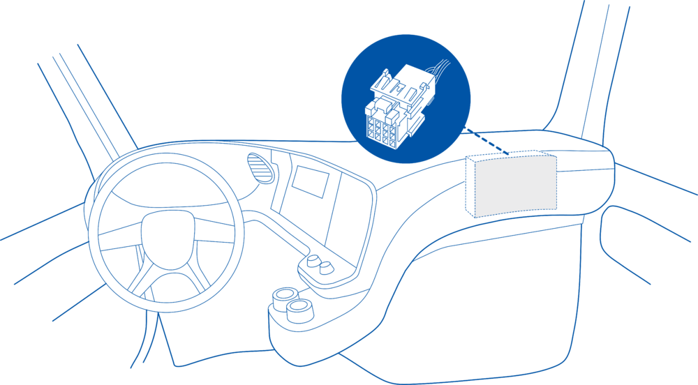
==== Behind the Fuse panel on passenger side – for Example SCANIA S/R/G/P Euro6 Series [[File:Scania R-series 1.3.png|frameless|1000x1000px]] ====
*Fixed occasional failures of firmware updates performed via the configuration tool, reducing the chance of interrupted or failed local updates.
*Fixed an issue where the device was not generating Iridium SBD records.
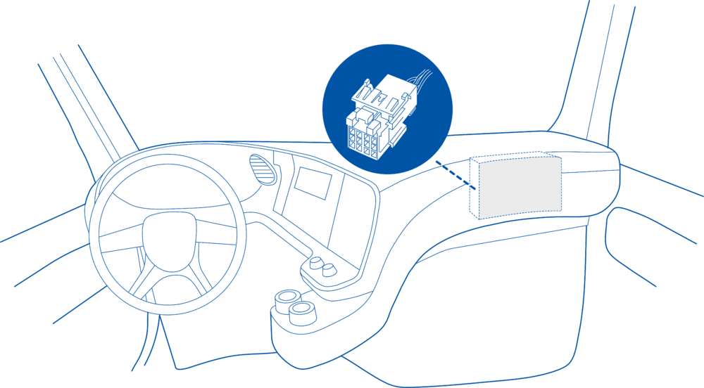
==== Near the Fuse panel on passenger side – for example DAF XF Euro6 [[File:DAF XF 1.3.png|frameless|1000x1000px]] ====
*Improved RS232 data sending to the Iridium module to ensure that SBD payloads are delivered reliably and without truncation.
'''Bluetooth / BLE'''
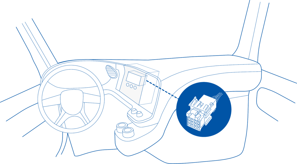
==== Behind the Radio on lower deck – for example Volvo FH Euro5 and Renault T Euro6 [[File:Volvo FH 1.3.png|frameless|1000x1000px]] ====
*Fixed cases where the device generated unnecessary beacon records in stop mode.
*Fixed issues where advanced beacon packet length information was not generated correctly in advanced beacon mode.
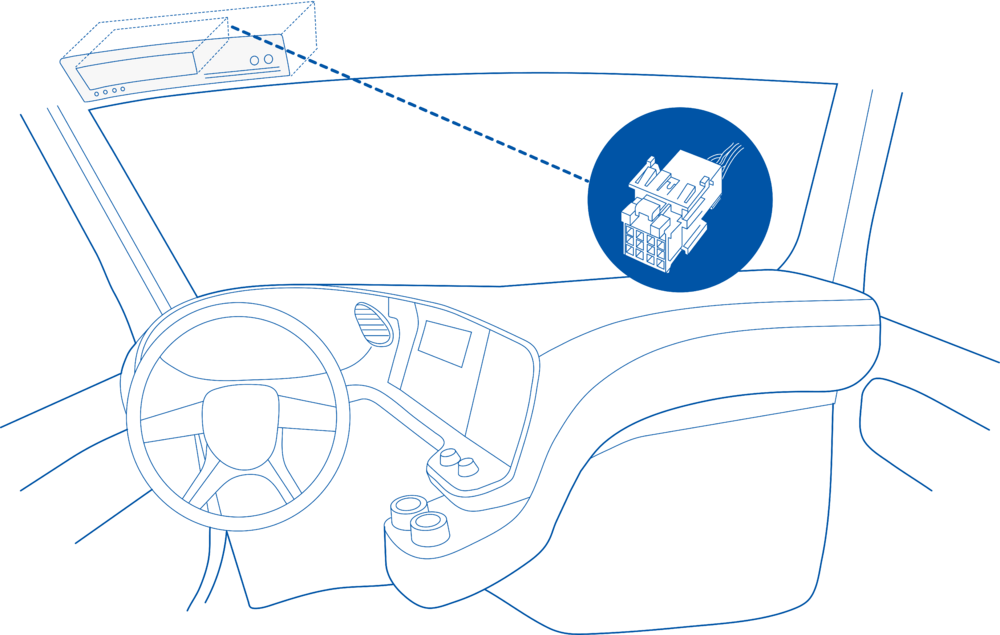
==== Behind the Tachograph on upper deck – for example Mercedes Actros MP5 Euro6 [[File:Mercedes Actros 1.3.png|frameless|1000x1000px]] ====
*Fixed incorrect reading of custom BLE parameter values when the data size was less than three bytes.
'''MQTT'''
* Fixed incorrect packing of MQTT packets containing multiple JSON objects when sending to cloud platforms.
==Device Configuration==
* Fixed an issue where the device did not send data via MQTT to custom cloud endpoints in some configurations.
1. Connect your OBD device to PC via USB or Bluetooth.<br>
* Fixed behaviour where long RS232 messages were not sent correctly via MQTT, which could cause truncation or loss when transmitted as JSON.
2. Open '''Teltonika Configurator''' and find your device in the list.<br>
* Improved long-term stability of MQTT JSON operation, increasing reliability for continuous cloud integrations and complex payloads.
3. Select your device from the list.<br>
'''Tachograph, K-Line & Driver/Company Data'''
4. Navigate to '''System''' and under '''System Settings''' Enable '''Codec 8 Extended''' protocol.<br>
* Implemented separate internal instance IDs for tachograph IO elements and DDD file downloading to avoid interference between live data and file download.
5. Open '''OBD II''' section on the left.<br>
* Fixed a problem where tachograph auto address selection did not work correctly.
6. In '''General''' -> '''OBD II Settings''' -> '''OBD Feature''' select '''ELD'''.<br>
* Fixed an issue where the working tachograph address could change unexpectedly after firmware updates, causing DDD download failures.
7. In '''OBD VIN settings'''-> '''VIN Source''' select prefered source. Some heavy duty vehicles may not automaticly provide VIN number, in that case we recommend to setup VIN manually.<br>
* Fixed errors where remote tachograph file download sessions could be interrupted or not start at all in certain conditions.
[[File:OBD II Settings.png|500x500px]]<br>
* Fixed behaviour where the tachograph company card number continued to be reported even after the card was removed.
8. Save the configuration by pressing '''Save to device''' on the top.<br>
* Fixed an issue where the tachograph Driver Name field was missing or incomplete in driver information data.
9. New section with J1939 parameters can be found in '''ELD''' section on the right bottom.<br>
* Improved character encoding for tachograph Driver Name, including extended and Nordic letters.
[[File:ELD Settings.png|500x500px]]<br>
* Fixed an issue where no data was received over K-Line, preventing tachograph and diagnostic data reception.
* Improved K-Line detection and privacy mode handling, including explicit privacy status reporting where applicable.
==Supported Parameter List==
* Enhanced tachograph-related logging and error handling to make diagnostics clearer.
* Fixed transmission of vehicle and driver identification values (such as VIN, VRN and driver identification) so that accurate identification data is always sent.
The full supported parameter list for OBD devices can be found in the following pages:
'''FMS / Manual CAN / CAN / Eco Driving & Vehicle Data'''
*[[FMB001 Teltonika Data Sending Parameters ID]]
* Fixed missing or incorrect reading of specific FMS parameters, including version-specific parameter sets.
*[[FMB003 Teltonika Data Sending Parameters ID]]
* Fixed fluctuating fuel levels when using FMS or CAN sources, improving fuel accuracy for both standard and EV FMS use cases.
*[[FMC003 Teltonika Data Sending Parameters ID]]
* Fixed issues where FMS-based speed was not being used correctly as the selected speed source.
*[[FMM003 Teltonika Data Sending Parameters ID]]
* Improved overall CAN stability so that tachograph CAN and FMS information is not lost due to CAN bus overflow.
*[[FMM00A Teltonika Data Sending Parameters ID]]
* Fixed incomplete or malformed responses to commands that start or stop Manual CAN (MCAN) transmissions, ensuring clear responses and reliable remote control.
* Ensured that Manual CAN requests and commands are no longer executed when ignition is OFF.
==Downloads==
'''New Features'''
This functionality requires the latest OBD [[Teltonika Configurator versions|configurator]] and [[Firmware versions#OBD trackers|firmware]] for optimal performance.
* NEW! Added support for storing and sending records from RAM memory. recommended for rapid data sending i.e. data saving every second etc. ([[FMC650 System settings#Records Saving/Sending Without TS|FMC650 System settings]])
* NEW! Implemented a new feature called the “one minute rule” for tachograph driving state, reducing unnecessary state toggling and improving driving/rest detection accuracy.([[FMC650 LVCAN I/O,FMS IO and Tachograph data elements#Driver Working State Filters|FMC650 Driver Working State Filters]])
For more information about '''OBD-II to FMS adapter''' specifications and ordering, please visit [https://www.teltonika-gps.com/products/accessories/data-cables/obd-ii-to-fms-adapter OBD-II TO FMS ADAPTER] web page.
* NEW! Trailer CAN functionality. ([[FMC650 TrailerCAN]])
* NEW! Implemented “scanevfms“ command for diagnosing electric trucks, providing targeted EV CAN diagnostics. ([[FMB scanevfms]])
* NEW! Implemented “can_info“ command that returns details of the CAN bus (baud rates, modes and other key parameters), aiding diagnostics. ([[FMB can_info]])
* NEW! Updated the “tachocheck“command to show more detailed information. ([[FMB tachocheck]])
'''Configuration, Parameters & Tools'''
* Fixed an issue where a single setparam command could not change multiple parameters at once.
* Fixed behaviour where the odometer command always returned a GNSS-based odometer value regardless of the configured odometer source.
* Fixed cases where the device disconnected unnecessarily from the configurator.
* Fixed an issue where the SIM PIN was not remembered after soft or hard reset.
</td>
</tr>
Latest revision as of 09:34, 8 May 2026
Introduction
Teltonika OBD devices are able to read data from heavy duty vehicles. With the OBD to FMS adapter, clients are able to connect OBD devices to their heavy duty vehicles which have FMS female connector (usually located under the front panel). Cable is only applicable with the European truck.
Cable pinout scheme
Cable pinout scheme:
OBD 16PF
FMS 12PM
4/5
=>
1
6
=>
6
14
=>
9
16
=>
12
DISCLAIMER:PLEASE MAKE SURE THE FMS PINOUT OF YOUR HEAVY DUTY VEHICLE IS AS REFERRED ON THE PROVIDED PINOUT SCHEME. IN CASE OF INCORRECT PINOUT PLEASE CONTACT YOUR HEAVY DUTY VEHICLE DEALERSHIP. THE CLIENT IS RESPONSIBLE FOR ALL THE ISSUES, WHICH MIGHT OCCUR BY INCORRECT INSTALLATION.
NOTE:Please use OBD devices with the latest firmware which has implemented J1939 protocol support.
FMS Plug Location
Even though the FMS cable is standardized cable – its placement in the vehicle might differ depending on manufacturer and depending on vehicle trim level.
These examples identify the most common locations for the FMS plug.
Behind the Fuse panel on passenger side – for Example SCANIA S/R/G/P Euro6 Series
Near the Fuse panel on passenger side – for example DAF XF Euro6
Behind the Radio on lower deck – for example Volvo FH Euro5 and Renault T Euro6
Behind the Tachograph on upper deck – for example Mercedes Actros MP5 Euro6
Device Configuration
1. Connect your OBD device to PC via USB or Bluetooth.
2. Open Teltonika Configurator and find your device in the list.
3. Select your device from the list.
4. Navigate to System and under System Settings Enable Codec 8 Extended protocol.
5. Open OBD II section on the left.
6. In General -> OBD II Settings -> OBD Feature select ELD.
7. In OBD VIN settings-> VIN Source select prefered source. Some heavy duty vehicles may not automaticly provide VIN number, in that case we recommend to setup VIN manually.
8. Save the configuration by pressing Save to device on the top.
9. New section with J1939 parameters can be found in ELD section on the right bottom.
Supported Parameter List
The full supported parameter list for OBD devices can be found in the following pages: